Supercharge Your Innovation With Domain-Expert AI Agents!

Tabbed separation clutch plate

A clutch plate and separator technology, used in clutches, friction clutches, fluid-driven clutches, etc., to solve problems such as multi-plate clutch drag and rotation loss

Active Publication Date: 2013-10-30
GM GLOBAL TECH OPERATIONS LLC
View PDF5 Cites 6 Cited by
  • Summary
  • Abstract
  • Description
  • Claims
  • Application Information

AI Technical Summary

Problems solved by technology

This can lead to drag and spin losses in multi-plate clutches

Method used


Image

  • Tabbed separation clutch plate
  • Tabbed separation clutch plate
  • Tabbed separation clutch plate

Examples


Embodiment Construction

[0053] The following description is merely exemplary in nature and is not intended to limit the invention, its application or uses.

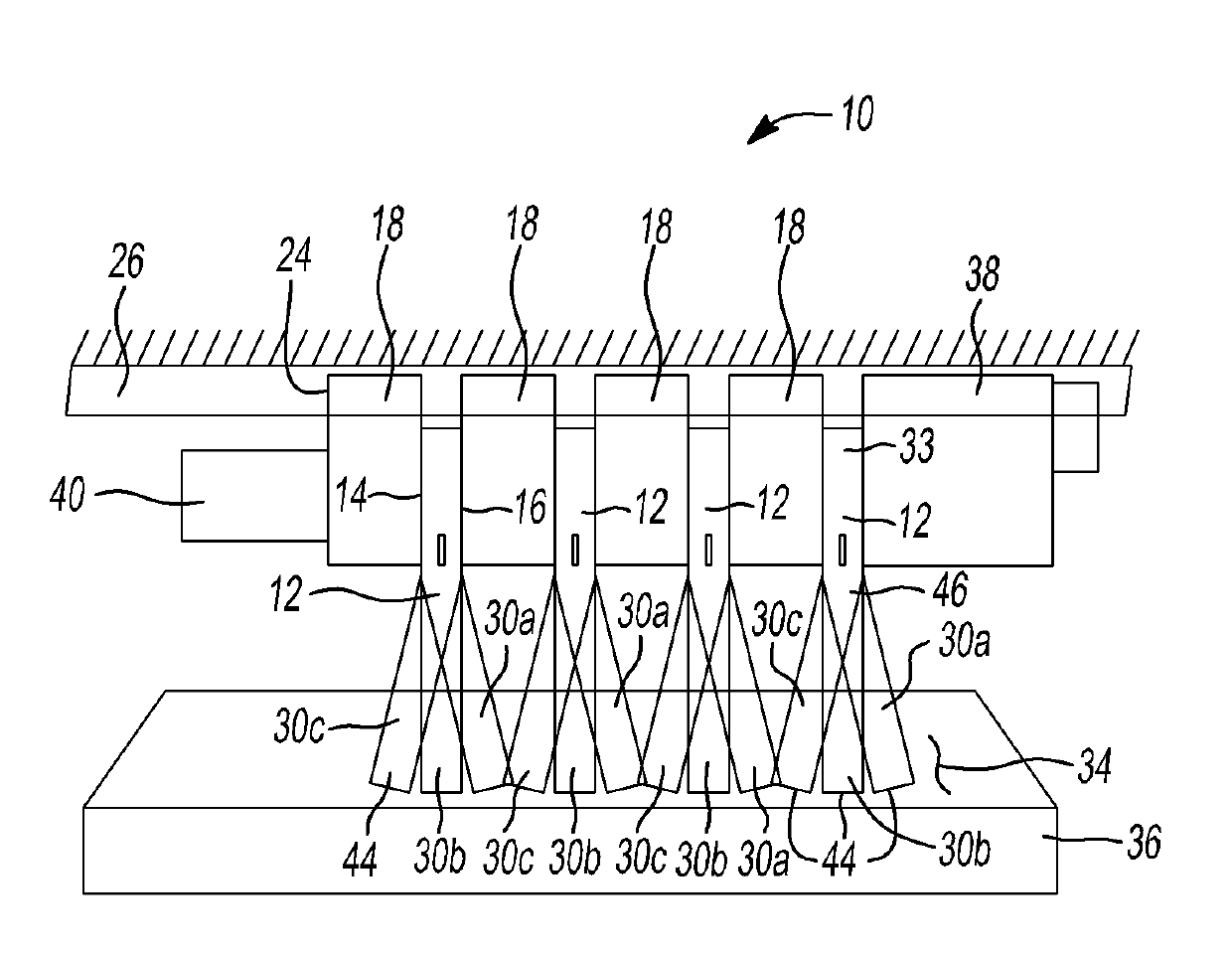
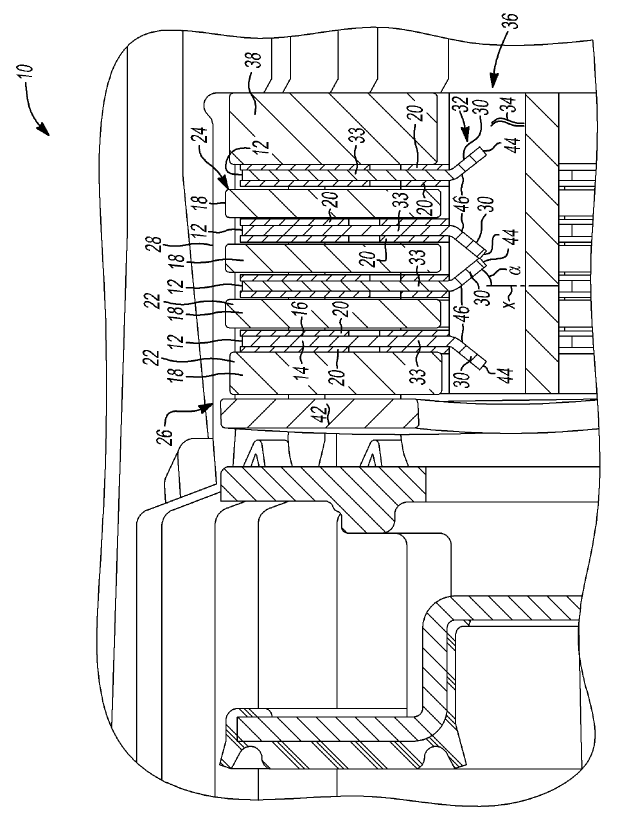
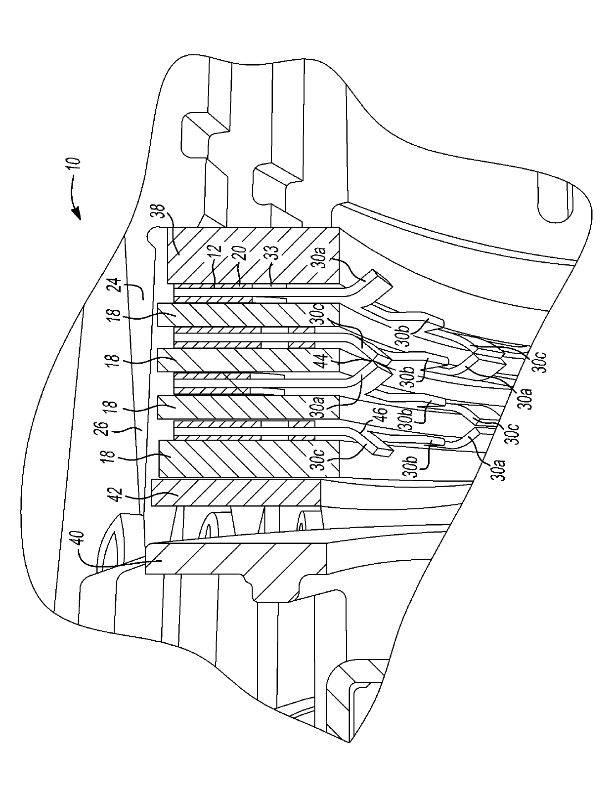
[0054] The present invention provides a multi-plate clutch assembly that reduces spin loss and drag within the plate clutches of the multi-plate clutch assembly by providing a separation force between the plates. Separation forces may additionally or alternatively be applied to the separator sheets. The separation force can be achieved by attaching a spring, such as a Belleville spring, to the chip (and / or separator sheet). The spring may be integrally formed with the chip (and / or separator sheet). For example, in one form the teeth of the blade are curved or formed at an acute angle relative to the plane of the blade. At least one tooth of a first piece contacts at least one tooth of a second adjacent piece when mounted, thereby providing a separation force between adjacent chips (and / or separator pieces).

[0055] see now Figure 1-4 , whe...


PUM


Abstract

The invention relates to a tabbed separation clutch plate. Concretely, a multiplate clutch assembly for use in an automotive powertrain is provided that includes a first member, a second member, a plurality of first clutch plates attached to the first member, and a plurality of second clutch plates attached to the second member. The first and second clutch plates are disposed alternatively with one another. At least two of the first clutch plates have separator portions that are configured to contact each other and provide a separation force therebetween. A clutch plate is also provided that includes an annular main body portion defining an aperature therethrough and defining and outer edge and an inner edge. Separator teeth extend from a tooth edge, the tooth edge being one of the inner and outer edges of the main body portion. Each separator tooth is bent at an acute angle with respect to the main body portion.

Description

[0001] Cross reference for related applications [0002] This application requires the rights and interests of temporary application of NO.61 / 624752 submitted on April 16, 2012.The public content of the above applications is referenced and incorporated into this application here. Technical field [0003] The invention involves car transmission components, and more specifically involves a clutch sheet for friction clutch components used for car transmission. Background technique [0004] The statement of this section only provides background information related to the present invention, which may not constitute or does not constitute existing technologies. [0005] The typical motor vehicle automatic transmission includes gear elements and multiple clutches. The multiple clutch can be selected and combined in order to establish one of several forward -speed ratios between the transmission input and the output shaft.The input shaft can be connected to the vehicle engine through the...

Claims


Application Information

Patent Timeline
Patent Type & Authority Applications(China)
IPC IPC(8): F16D13/68
CPCF16D13/69F16D13/52F16D13/648F16D25/0638F16D13/58
Inventor R.A.久尔达
Owner GM GLOBAL TECH OPERATIONS LLC
Features
  • R&D
  • Intellectual Property
  • Life Sciences
  • Materials
  • Tech Scout
  • Unparalleled Data Quality
  • Higher Quality Content
  • 60% Fewer Hallucinations
Learn More