Member installation apparatus and member shape identification method

A technology for installing devices and components, which is applied in the direction of measuring devices, optical devices, instruments, etc., can solve the problems of increased production takt time, time spent, and production takt loss

Inactive Publication Date: 2013-10-30
PANASONIC CORP
View PDF1 Cites 4 Cited by
  • Summary
  • Abstract
  • Description
  • Claims
  • Application Information

AI Technical Summary

Problems solved by technology

[0007] However, in the method of stopping the mounting head or moving the mounting head at a constant speed in order to image the measurement site of the component, it takes time to image the component.
In particular, in the component mounting apparatus, the measurement site of the component is imaged during the period from suctioning the component from the component box to mounting on the board. If the mounting head is stopped or moved at the same speed, there is a problem of tact loss (increase in tact time) when mounting components on the substrate

Method used


Image

  • Member installation apparatus and member shape identification method
  • Member installation apparatus and member shape identification method
  • Member installation apparatus and member shape identification method

Examples


Embodiment Construction

[0061] Hereinafter, a component mounting device according to an embodiment of the present invention will be specifically described with reference to the drawings.

[0062] In addition, the embodiment described below shows a specific example of the present invention. Numerical values, shapes, materials, constituent elements, arrangement positions and connection forms of constituent elements, steps, order of steps, etc. shown in the following embodiments are examples, and are not intended to limit the present invention. In addition, among the constituent elements of the following embodiments, constituent elements not described in the independent claims representing the highest concept will be described as arbitrary constituent elements.

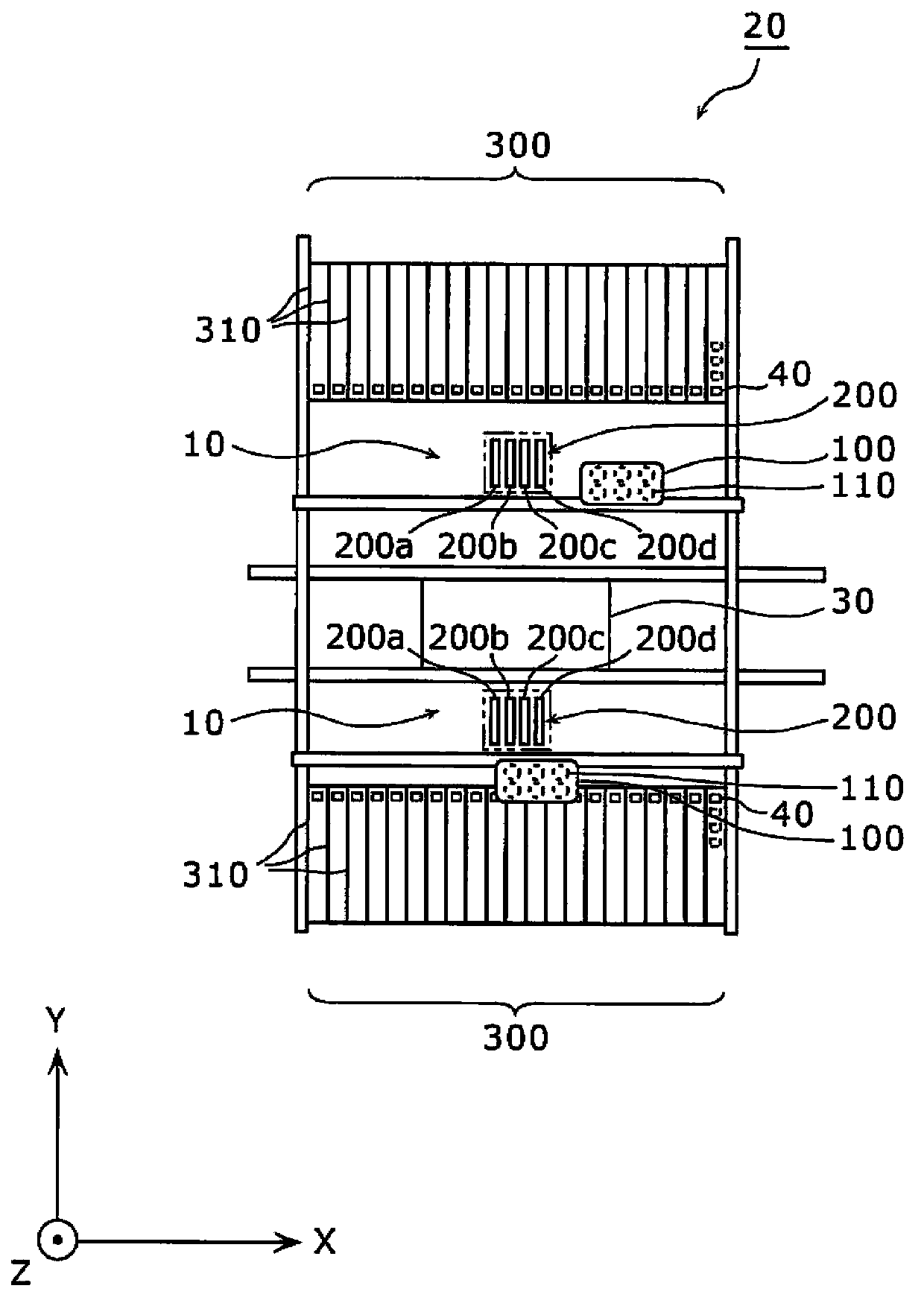
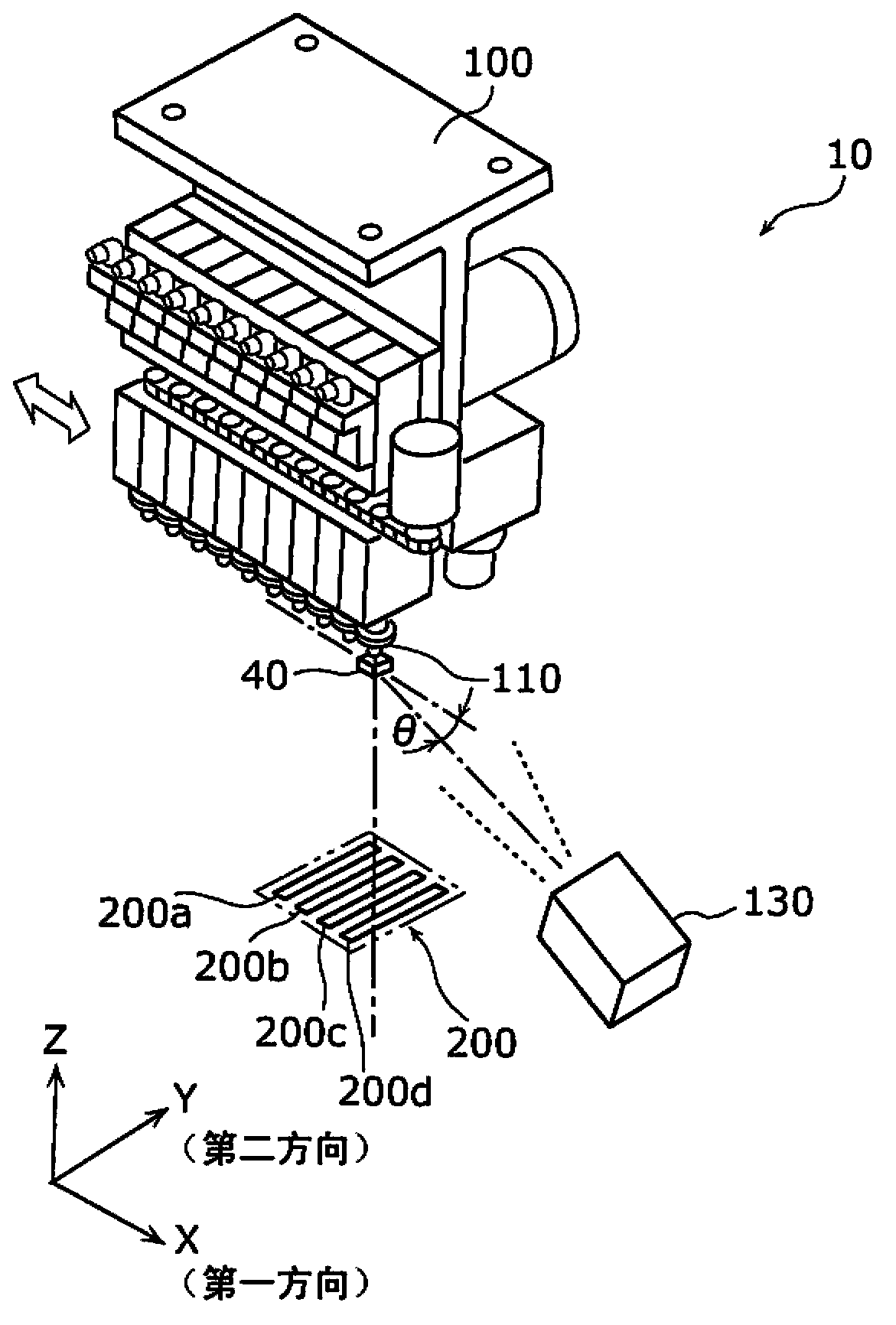
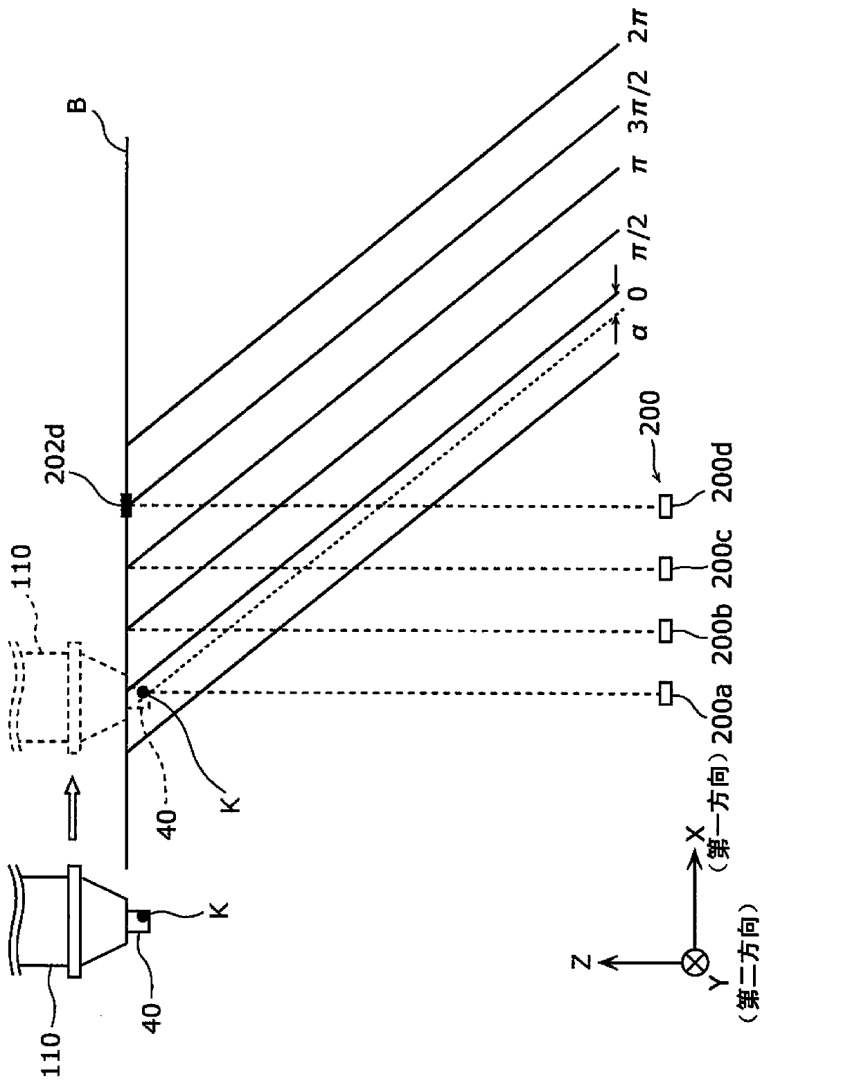
[0063] figure 1 It is a plan view showing the internal main configuration of the component mounting device according to the present embodiment.

[0064] The component mounting device 20 is a device for mounting the component 40 on the substra...


PUM


Abstract

The invention provides a member installation apparatus and a member shape identification method, wherein the apparatus comprises a shooting part (200); a position check part (140) that checks position of a holding member on a first direction that is held by an installation head (100) that moves while speeding up in the first direction, wherein the first direction crosses with the length direction of a plurality of linear area shooting parts of the shooting part; an irradiation part (130) that irradiates light to a shooting object area, wherein the brightness of the light changes based on position of the first direction and is evenly distributed along a second direction crossing the first direction; a shooting timing controlling part (150) that outputs shooting instruct signal based on the check result of the position check part when the holding member reaches a position when it can be shot by each linear area shooting part; and a shape identification part (180) that identifies shape of the holding member according to the image of the holding member that is used as the shooting result.

Description

technical field [0001] The present invention relates to a component mounting device for mounting components on a substrate, and more particularly to a component mounting device for three-dimensionally measuring the shape of an object such as a component. Background technique [0002] A mounted substrate production system for producing a mounted substrate on which components are mounted includes a component mounting device that mounts components on the substrate, an inspection device that inspects the components mounted on the substrate, and the like. In the component mounting device, in order to improve the mounting accuracy of the components, the shape of the component attracted to the nozzle is recognized before the component is mounted. In addition, in the inspection apparatus, the shape of the component on the substrate is recognized in order to inspect the mounting state of the component on the substrate. Therefore, in order to produce mounting substrates with high pre...

Claims


Application Information

Patent Timeline
Patent Type & Authority Applications(China)
IPC IPC(8): G01B11/24
Inventor 小仓环树持田芳典佐藤勇一
Owner PANASONIC CORP
Why Eureka
Try Eureka