Mechanical pipette

A pipette, mechanical technology, applied in the direction of instruments, laboratory utensils, measuring tubes/pipettes, etc., can solve the complex tasks of creating routines and programs that are difficult to master, reduce ease of operation, and pipettes are difficult to manipulate and other issues to achieve the effects of extensive display, space saving, and economical manufacturing

Active Publication Date: 2013-10-30
EPPENDIRF AG
View PDF18 Cites 6 Cited by
  • Summary
  • Abstract
  • Description
  • Claims
  • Application Information

AI Technical Summary

Problems solved by technology

This makes the pipette difficult to maneuver and presents a possible risk of misuse
In addition, the operating and display unit constitutes a large part of the cost of the pipette
Complex tasks such as creating routines and programs via the integrated operating and display unit are difficult to master
This further reduces ease of use if the pipette is configured with a small operating and display unit

Method used


Image

  • Mechanical pipette
  • Mechanical pipette
  • Mechanical pipette

Examples


Embodiment Construction

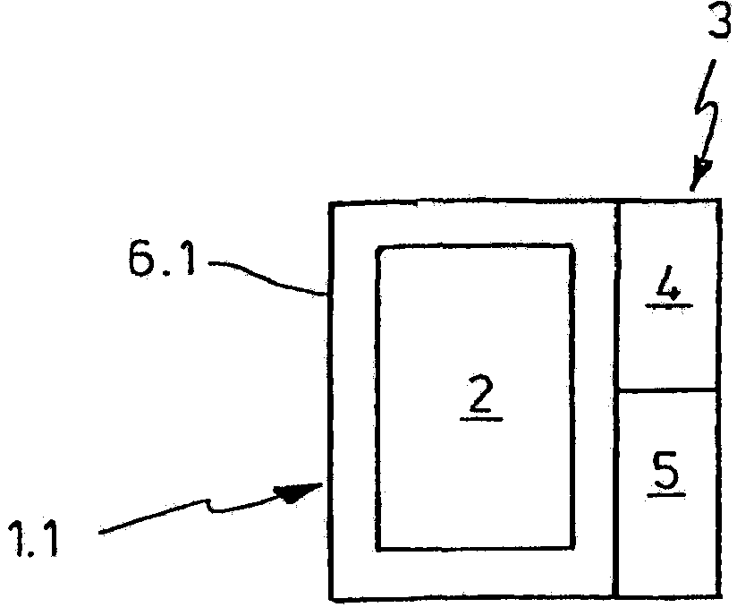
[0084] according to figure 1 , a conventional pipette 1.1 has a unit 2 for pipetting liquids and an operating and display unit 3 . The operation and display unit 3 includes an operation unit 4 and a display unit 5 . The unit 2 for pipetting liquid and the operating and display unit 3 are physically combined in a common housing 6.1.

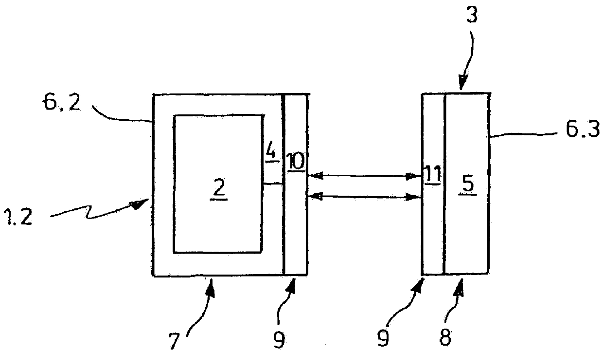
[0085] For the basis Figure 2a In the pipette 1.2 according to the invention, the unit 2 for pipetting and the operating unit 4 are part of a device module 7 with a small housing 6.2. The display unit 5 is accommodated in a housing 6 . 3 of the display module 8 which is completely physically separate from the device module 7 .

[0086] Furthermore, the device module 7 and the display module 8 have a device 9 for wireless communication, which includes an interface 10 for wireless communication of the device module 7 and an interface 11 for wireless communication of the display module 8 .

[0087] The pipette has a one-way device 9 for wireless...


PUM

PropertyMeasurementUnit
heightaaaaaaaaaa
heightaaaaaaaaaa

Abstract

A mechanical pipette comprising: a. a manually drivable mechanical unit for pipetting liquids, b. at least one sensor for detecting operating and / or performance data, c. an operating unit, and d. a display unit, e. wherein a device module comprises the mechanical unit for pipetting, the sensor and operating unit, f. a display module physically separate from the device module completely or partially comprises the display unit, and g. means for wireless communication between the device module and the display module.

Description

technical field [0001] The present invention relates to mechanical pipettes. Background technique [0002] A pipette is a hand-held or stationary dispensing device used especially in laboratories for dispensing liquids. "Liquid" means a liquid medium in the form of a sample that is a single-phase liquid or a liquid mixture or a multi-phase liquid mixture (such as an emulsifier) ​​or a liquid-solid mixture (such as a suspension) or a liquid-gas mixture (such as a foam). [0003] An air displacement pipette has a mount for releasably holding the pipette tip. The displacement unit for the air is integrated in the pipette and is connected to the hole in the base through the communication of the channel. The air cushion is displaced by the displacement unit so that, depending on the displacement direction of the air cushion, liquid is sucked into and discharged from the end opening in the pipette tip. The displacement unit is generally a cylinder with a piston displaceable the...

Claims


Application Information

Patent Timeline
Patent Type & Authority Applications(China)
IPC IPC(8): G01N35/00B01L3/02
CPCB01L3/0213B01L2300/025B01L2300/024B01L3/021B01L2300/023B01L3/0237
Inventor G·A·莫尔B·冯拜希曼W·卢尔兹
Owner EPPENDIRF AG
Why Eureka
Try Eureka