
Device for return transmission networking

A technology for networking and installation benchmarks, applied in the field of communications, can solve problems such as difficulty in commissioning and installation, long network construction and commissioning cycle, etc., to avoid reversing procedures and improve network construction efficiency.

Inactive Publication Date: 2015-01-21
HUAWEI TECH CO LTD
View PDF7 Cites 0 Cited by
  • Summary
  • Abstract
  • Description
  • Claims
  • Application Information

AI Technical Summary

Problems solved by technology

However, in the existing technology, during network construction and deployment, after installing the backhaul networking device, it is necessary to power on both ends of the link to perform on-site antenna exchange, so it is difficult to debug and install, and the network construction and debugging cycle is long

Method used


Image

  • Device for return transmission networking
  • Device for return transmission networking
  • Device for return transmission networking

Examples


Embodiment Construction

[0025] The following will clearly and completely describe the technical solutions in the embodiments of the present invention with reference to the drawings in the embodiments of the present invention. Obviously, the described embodiments are part of the embodiments of the present invention, not all of them. Based on the embodiments of the present invention, all other embodiments obtained by persons of ordinary skill in the art without creative efforts shall fall within the protection scope of the present invention.

[0026] The technical solutions of the embodiments of the present invention can be applied to various backhaul networks, such as LTE small cell backhaul networks.

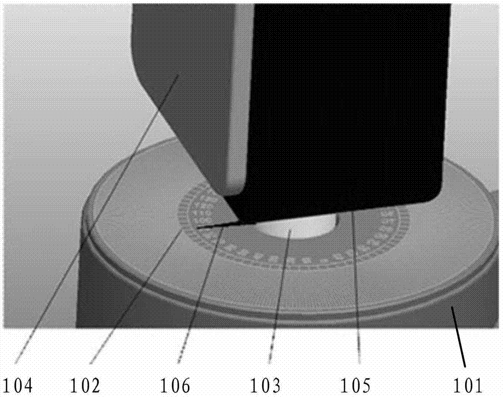
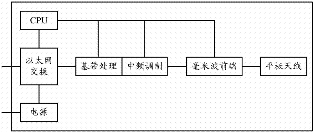
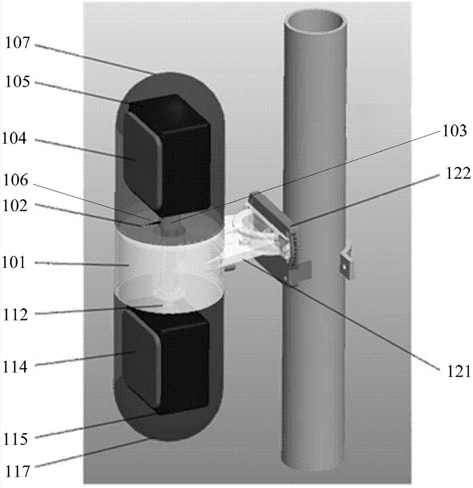
[0027] figure 1 is a schematic structural diagram of a device for backhaul networking according to an embodiment of the present invention. Such as figure 1 , the device consists of:

[0028] Baseband unit 101; the first dial 102 positioned on the baseband unit 101; the first rotating shaft 103, the ...


PUM


Abstract

Disclosed is a device for backhaul networking. The device comprises: a baseband unit (101); a first dial (102) located on the baseband unit (101); a first rotating shaft (103) perpendicular to the plane of the first dial (102) and capable of rotating relative to the baseband unit (101); a first planar antenna (104); a first millimeter-wave front-end unit (105), with the first planar antenna (104) and the first millimeter-wave front-end unit (105) being connected together and fixed on the first rotating shaft (103), and the normal line of the plane of the first planar antenna (104) being perpendicular to the first rotating shaft (103); and a first pointer (106) fixed on the first rotating shaft (103), and when the first rotating shaft (103) rotates, the first pointer (106) indicates the direction angle of the first planar antenna (104) on the first dial (102). The device for backhaul networking of the embodiments of the present invention can avoid the process of field antenna swapping, improving the networking efficiency.

Description

technical field [0001] The present invention relates to the communication field, and more particularly, to a device for backhaul networking. Background technique [0002] In order to meet the ever-increasing bandwidth demands of mobile users, the 3rd Generation Partnership Project (3rd Generation Partnership Project, referred to as "3GPP") proposed the Long Term Evolution (referred to as "LTE") technology to continuously improve the wireless network access capacity. In order to meet the challenge of large-capacity access in urban hotspots, a small cell (Small Cell) technology is proposed to increase access capacity and spectrum efficiency by deploying more base stations in hotspots. [0003] In the hot spot (Hot Spot) area, small cells are usually deployed densely, and are generally deployed along urban streets to cover a range of 50-300m, and at a height of 3-6m above the street level. Since they are all deployed outdoors and in densely populated commercial areas, small c...

Claims


Application Information

Patent Timeline
Patent Type & Authority Patents(China)
IPC IPC(8): H01Q3/04H01Q21/00
CPCH01Q9/0407H01Q3/02H01Q3/04
Inventor 蒲剑岳勇李宁
Owner HUAWEI TECH CO LTD
Learn More