Equipment dehumidification method, condensation detection device and equipment

A detection device and equipment technology, applied in lighting and heating equipment, drying gas arrangement, drying solid materials, etc., can solve the problems of uncertainty of standing time, equipment condensation, easy rupture of packaging bags, etc., to reduce dehumidification time, The effect of less cost and avoiding condensation problems

Inactive Publication Date: 2013-11-20
HUAWEI TECH CO LTD
View PDF4 Cites 14 Cited by
  • Summary
  • Abstract
  • Description
  • Claims
  • Application Information

AI Technical Summary

Problems solved by technology

[0004] The existing technology also has the following defects: the cost of vacuum packaging and sealing is increased, and it also needs to be left to stand for processing. Due to the risk of the packaging bag being easily broken, the standing time is also uncertain. If the standing time is too long, it will affect the equipment. The installation, if the standing time is not enough, unpack the package, the equipment still has the problem of condensation

Method used


Image

  • Equipment dehumidification method, condensation detection device and equipment
  • Equipment dehumidification method, condensation detection device and equipment
  • Equipment dehumidification method, condensation detection device and equipment

Examples


Embodiment Construction

[0057]In order to make the purpose, technical solutions and advantages of the embodiments of the present invention clearer, the technical solutions in the embodiments of the present invention will be clearly and completely described below in conjunction with the drawings in the embodiments of the present invention. Obviously, the described embodiments It is a part of embodiments of the present invention, but not all embodiments. Based on the embodiments of the present invention, all other embodiments obtained by persons of ordinary skill in the art without making creative efforts belong to the protection scope of the present invention.

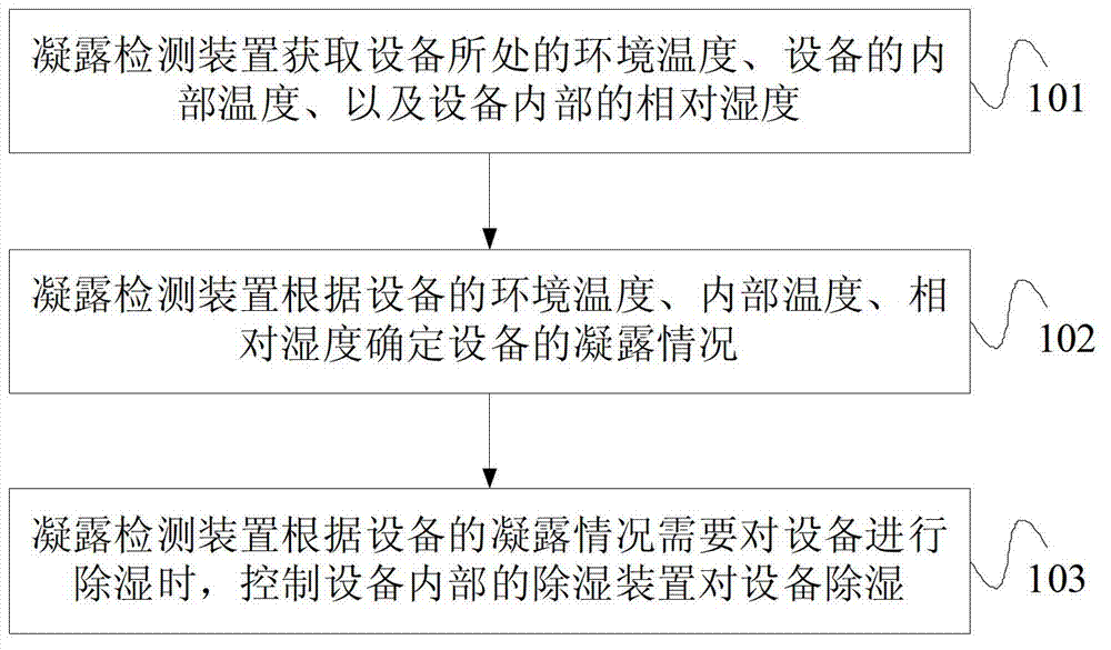
[0058] figure 1 The flow chart of the first embodiment of the method for dehumidifying the equipment of the present invention, such as figure 1 As shown, the method provided in this embodiment includes the following steps:

[0059] Step 101, the condensation detecting device acquires the ambient temperature where the device is located, the i...


PUM


Abstract

An embodiment of the invention provides an equipment dehumidification method, a condensation detection device and equipment. The method includes that the condensation detection device acquires environment temperature at a position of the equipment, internal temperature of the equipment and relative humidity of the inner portion of the equipment, determines the condensation conditions of the equipment according to the environment temperature, the internal temperature and the relative humidity of the equipment, and controls a dehumidification device inside the equipment to dehumidify the equipment when dehumidifying the equipment according to the condensation conditions of the equipment. According to the method, the condensation detection device acquires the environment temperature, the internal temperature and internal humidity of the equipment, determines the condensation conditions of the inner portion of the equipment, and controls the dehumidification device inside the equipment to dehumidify the equipment according to the condensation conditions of the equipment, so that the problem of condensation can be effectively avoided.

Description

technical field [0001] Embodiments of the present invention relate to equipment, and in particular, to a method for dehumidifying equipment, a condensation detection device, and equipment. Background technique [0002] As air transportation becomes more and more common and the integration of equipment is increasing, some high-end equipment may be directly transported from some high-temperature and high-humidity environments to low-temperature environments in just a few hours, and then moved to the air-conditioning room. The low-temperature environment is directly transported to the high-temperature and high-humidity environment for installation. The installation environment of the equipment has strict temperature and humidity requirements. When the equipment enters the low-temperature environment from the high-temperature and high-humidity environment, a large amount of condensation will appear on the surface of the equipment, the internal structure of the equipment, and the ...

Claims


Application Information

Patent Timeline
Patent Type & Authority Applications(China)
IPC IPC(8): F26B25/00F26B21/00
Inventor 李小川
Owner HUAWEI TECH CO LTD
Why Eureka
Try Eureka