Energy-saving baking room with dehumidifying and heat accumulating function

A technology of barn and moisture outlet, which is applied in the field of energy-saving barn, which can solve the problems of high smoke density, prolonged dehumidification time, and energy waste, so as to reduce heat waste, improve heat energy utilization rate, and shorten dehumidification time Effect

Inactive Publication Date: 2014-12-10
TOBACCO RES INST OF HUBEI PROVINCE
View PDF3 Cites 0 Cited by
  • Summary
  • Abstract
  • Description
  • Claims
  • Application Information

AI Technical Summary

Problems solved by technology

[0002] The barn is a building that is heated by fuel and bakes items. Most of the barns take away most of the heat due to the need for moisture removal, which greatly wastes energy such as coal, especially the humidity of the flue-cured room. Due to the particularity of tobacco leaf curing in large barns, it needs a lot of dehumidification during the late yellowing period, color fixing period, and tendon drying period. The total time can reach more than 60 hours, and the waste of heat is very serious, resulting in waste of energy
Especially for dense barns with high smoke density, the smoke density is high, and there are fans for forced ventilation circulation. When the cold air door is opened to dehumidify, there will be a problem that the humid air cannot be discharged in time when it returns from the return air port, making the dehumidification Prolonged time will cause waste of heat or delay in dehumidification, resulting in roasting of tobacco leaves

Method used


Image

  • Energy-saving baking room with dehumidifying and heat accumulating function
  • Energy-saving baking room with dehumidifying and heat accumulating function
  • Energy-saving baking room with dehumidifying and heat accumulating function

Examples


Embodiment Construction

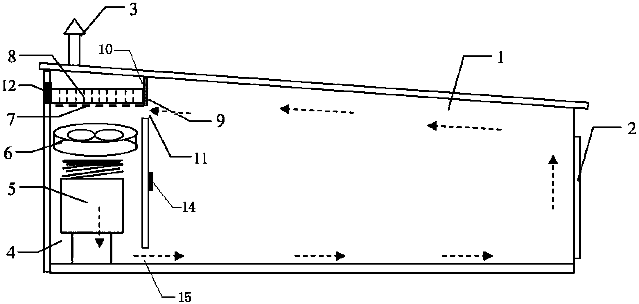
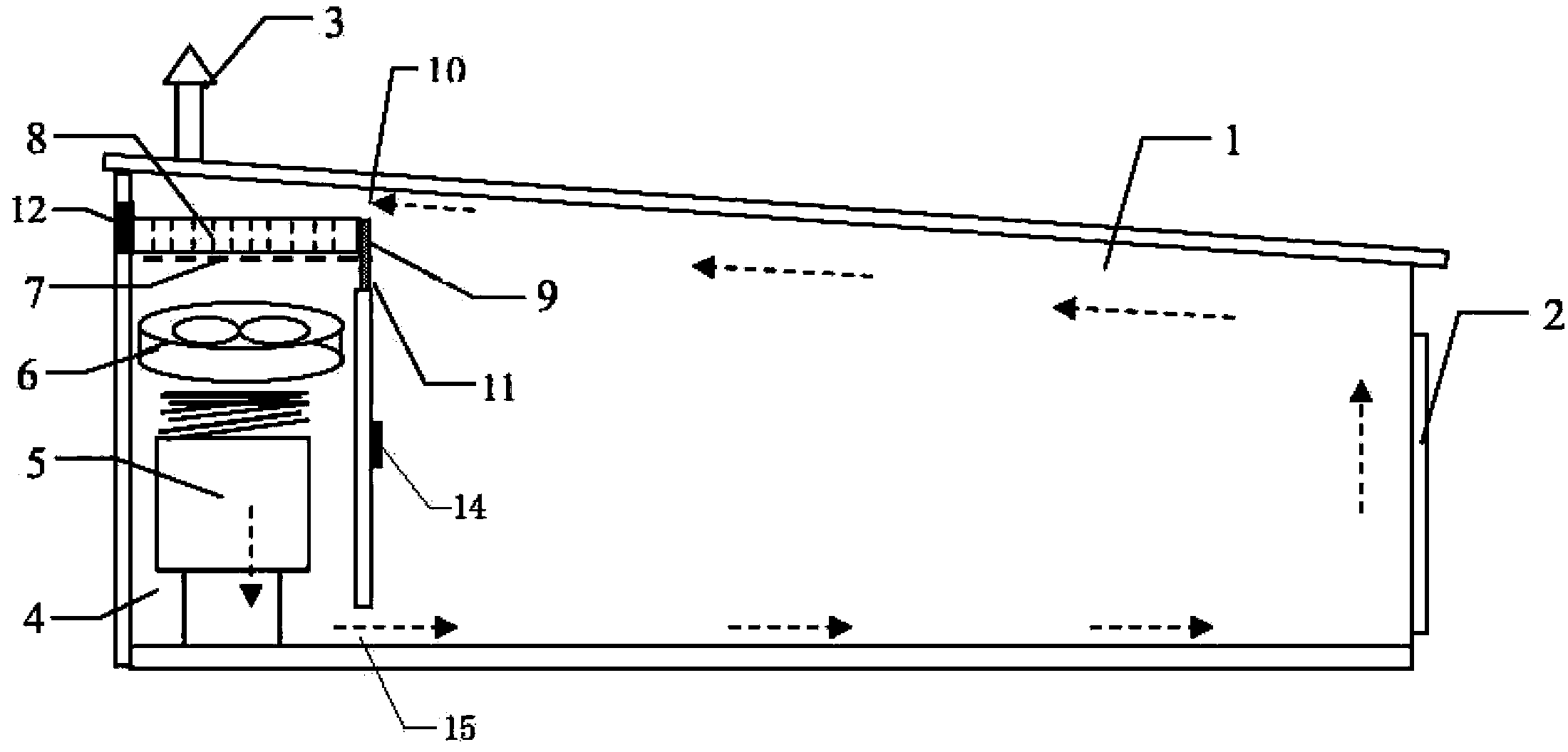
[0021] The present invention will be further described below in conjunction with accompanying drawing. figure 1 Among them, the energy-saving barn for dehumidification and heat retention includes a baking room 1 and a heating room 4, a moisture outlet is opened on the baking room 1, a chimney 3 is provided on the heating room 4, and a heating room 4 is provided with The heating furnace 5 and the fan 6 are provided with an air return port 11 and a moisture discharge port 10 between the heating chamber and the baking chamber. Between the baking room and the position higher than the air return port 11, in order to facilitate the air circulation and dehumidification, the moisture discharge port 10 is set near the top of the baking room. The position adjacent to the wet port 10, the distance between the two openings is equal to the height of the moisture discharge device; the moisture absorption device is composed of a porous support plate 7 and a moisture absorption plate 8, and t...


PUM


Abstract

The invention provides an energy-saving baking room with a dehumidifying and heat accumulating function. The energy-saving baking room comprises a baking chamber and a heating chamber, wherein the baking chamber is provided with a dehumidifying port, and the heating chamber is provided with a chimney. A heating furnace and a fan are arranged in the heating chamber, and an air return port is arranged between the heating chamber and the baking chamber. The energy-saving baking room is characterized in that a dehumidifying device is arranged in the inner upper side of the heating chamber, the dehumidifying port is arranged between the heating chamber and the baking chamber and higher than the air return port, the dehumidifying device comprises a porous humidity-absorbing support plate and a humidity-absorbing plate, the humidity-absorbing plate is fixed in the heating chamber and higher than the air return port but lower than the dehumidifying port and divides the heating chamber into two spaces, and automatic adjusting windshield plates capable of moving vertically and opposite in folding and unfolding state are arranged at the air return port and the dehumidifying port. By matching the dehumidifying device on the upper portion of the heating chamber with the automatic adjusting windshield plates, dehumidifying of the baking room can be accelerated, heat can be prevented from discharging along with humidity during dehumidifying, heat waste is reduced and heat utilization rate of the baking room is effectively improved.

Description

technical field [0001] The invention belongs to a flue-cured tobacco equipment, in particular to an energy-saving barn for dehumidification and heat retention, which can accelerate the dehumidification and reduce the waste of heat caused by the dehumidification. Background technique [0002] The barn is a kind of building that is heated by fuel and bakes items. Most of the barns take away most of the heat due to the need for moisture removal, which greatly causes waste of energy such as coal, especially the humidity of the flue-cured room is particularly high. Due to the particularity of tobacco leaf curing in large barns, it needs a lot of dehumidification during the late yellowing period, color fixing period, and tendon drying period. The time can reach more than 60 hours in total, and the waste of heat is very serious, thereby causing waste of energy. Especially for dense barns with high smoke density, the smoke density is high, and there are fans for forced ventilation ...

Claims


Application Information

Patent Timeline
Patent Type & Authority Patents(China)
IPC IPC(8): A24B3/10A24B3/04
Inventor 陈振国王玉军孙光伟李进平李建平祖秉桥高加明孙敬国
Owner TOBACCO RES INST OF HUBEI PROVINCE
Why Eureka
Try Eureka