Double circulation energy saving drying equipment with humidity discharging function
A drying equipment and double-cycle technology, applied in the direction of static material dryer, drying gas arrangement, local stirring dryer, etc., can solve the problems of low drying efficiency, heat waste, poor drying effect, etc.
- Summary
- Abstract
- Description
- Claims
- Application Information
AI Technical Summary
Problems solved by technology
Method used
Image
Examples
Embodiment 1
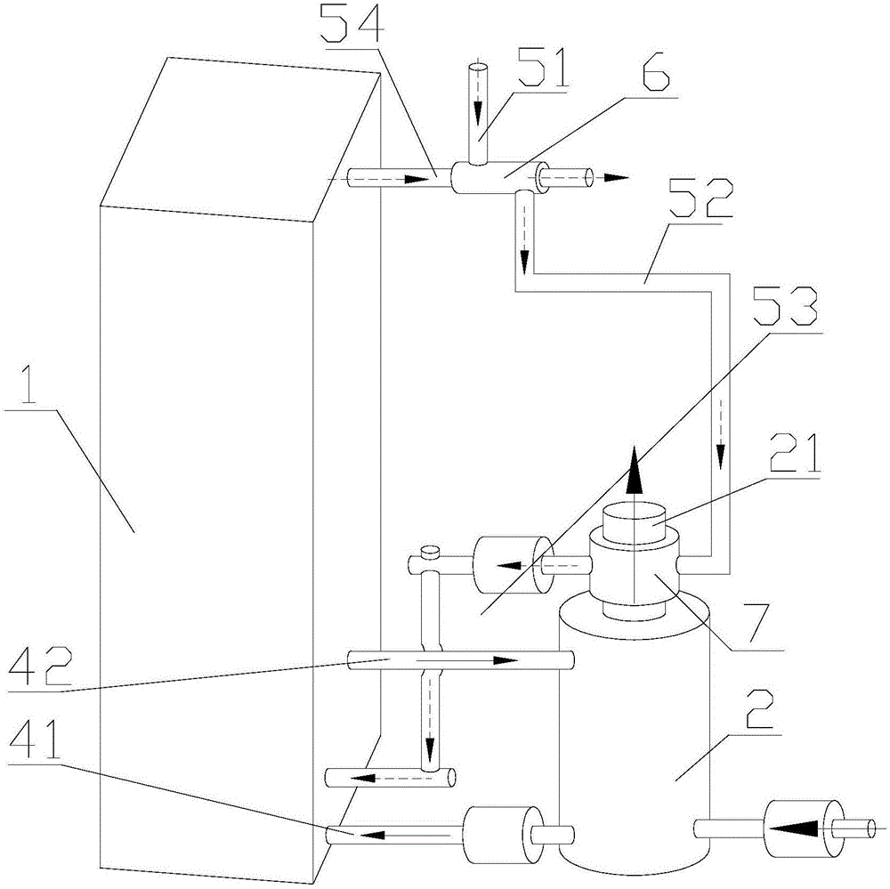
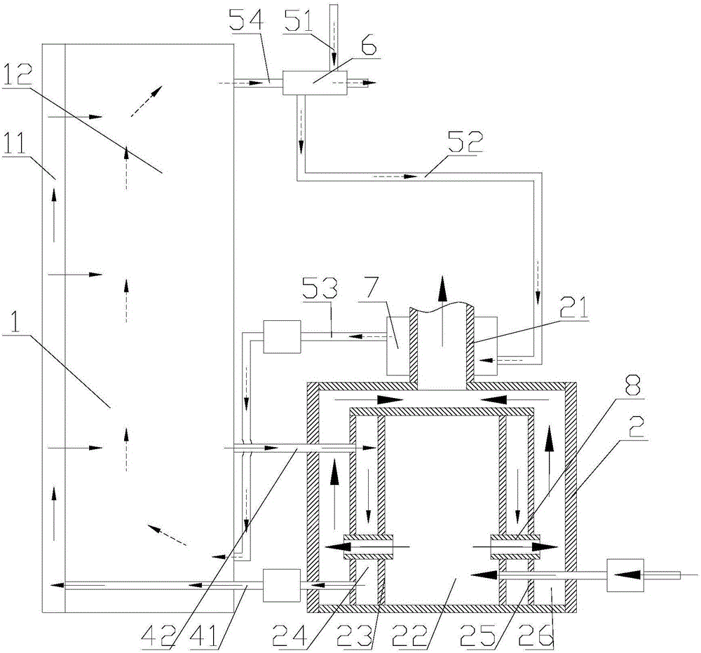
[0044] A dual-cycle energy-saving drying device with a dehumidification function, comprising a drying device 1 and a heat source supply device 2, between the drying device 1 and the heat source supply device 2, a main circulation pipeline for raising the temperature in the drying device 1 is arranged, The main circulation pipeline can continuously transmit the heat energy in the heat source supply device 2 to the drying device 1 and increase the temperature in the drying device 1, so as to achieve the purpose of drying. The drying device 1 is provided with a moisture exhaust pipe 54 for exhausting moisture, and the humid and hot air in the drying device 1 will finally be exhausted through the moisture exhaust pipe 54 . In addition, a dehumidification pipeline is also provided, and the dehumidification pipeline communicates with the drying device 1 after exchanging heat with the heat source supply device 2 or the moisture exhaust pipe 54 .
Embodiment 2
[0046] On the basis of the first embodiment, the main circulation pipeline includes a main circulation air intake pipe 41 and a main circulation air outlet pipe 42. One ends of the main circulation air intake pipe 41 and the main circulation air outlet pipe 42 are both connected to the heat source supply device 2. In the heat exchange chamber 24, the other ends of the main circulation air inlet pipe 41 and the main circulation air outlet pipe 42 are all connected to the drying device 1; A cycle for transferring heat energy is formed between them. When the drying equipment is working, the fan located on the main circulation pipeline works, the hot air in the heat source supply device 2 will enter the drying device 1 through the main circulation air intake pipe 41, and the cold air in the drying device 1 will pass through the main circulation air outlet pipe 42 enters the heat exchange chamber 24 of the heat source supply device 2, and absorbs the heat generated by the flue gas ...
Embodiment 3
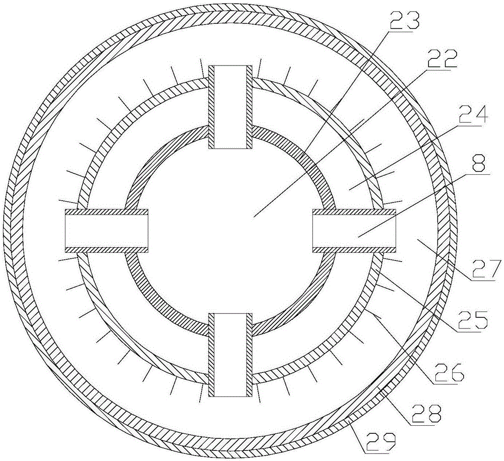
[0048] On the basis of Embodiment 1 or Embodiment 2, the heat source supply device 2 adopts the heat source supply device 2 that burns biomass fuel, and the heat source supply device 2 includes a combustion cylinder 23 and a heat dissipation cylinder which are sequentially sleeved from the inside to the outside. 25 and the outer shell 28, and form a combustion chamber 22, a heat exchange chamber 24 and a flue chamber 27 in the combustion cylinder 23, between the combustion cylinder 23 and the heat dissipation cylinder 25, and between the heat dissipation cylinder 25 and the outer casing 28, The heat exchange chamber 24 is communicated with the main circulation air inlet pipe 41 and the main circulation air outlet pipe 42 , the combustion chamber 22 is communicated with the flue chamber 27 through the flue connecting pipe 8 , and the flue chamber 27 is communicated with the chimney 21 . The heat source supply device 2 is provided with a combustion chamber 22, a heat exchange cha...
PUM
 Abstract
Description
Claims
Application Information
 - R&D
- Intellectual Property
- Life Sciences
- Materials
- Tech Scout
- Unparalleled Data Quality
- Higher Quality Content
- 60% Fewer Hallucinations
Browse by: Latest US Patents, China's latest patents, Technical Efficacy Thesaurus, Application Domain, Technology Topic, Popular Technical Reports.
© 2025 PatSnap. All rights reserved.Legal|Privacy policy|Modern Slavery Act Transparency Statement|Sitemap|About US| Contact US: help@patsnap.com


