Phase-locked loop rapid frequency band switching method and phase-locked loop circuit with frequency band switching function

A technology of switching circuits and phase-locked loops, applied in the direction of electrical components, automatic power control, etc., can solve the problems of frequency band switching, misjudgment, etc.

Active Publication Date: 2013-11-20
KUNSHAN BRANCH INST OF MICROELECTRONICS OF CHINESE ACADEMY OF SCI
View PDF5 Cites 4 Cited by
  • Summary
  • Abstract
  • Description
  • Claims
  • Application Information

AI Technical Summary

Problems solved by technology

[0005] In view of this, the present invention provides a phase-locked loop fast frequency band switching method and a phase-locked loop circuit for frequency band switching, to overcome the problem in the prior art that due to misjudgment of frequency band switching when under-damping, resulting in wrong switching of frequency bands

Method used


Image

  • Phase-locked loop rapid frequency band switching method and phase-locked loop circuit with frequency band switching function
  • Phase-locked loop rapid frequency band switching method and phase-locked loop circuit with frequency band switching function
  • Phase-locked loop rapid frequency band switching method and phase-locked loop circuit with frequency band switching function

Examples


Embodiment Construction

[0030] The following will clearly and completely describe the technical solutions in the embodiments of the present invention with reference to the accompanying drawings in the embodiments of the present invention. Obviously, the described embodiments are only some, not all, embodiments of the present invention. Based on the embodiments of the present invention, all other embodiments obtained by persons of ordinary skill in the art without making creative efforts belong to the protection scope of the present invention.

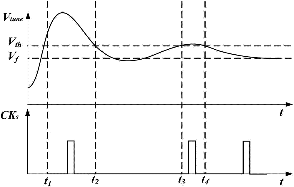
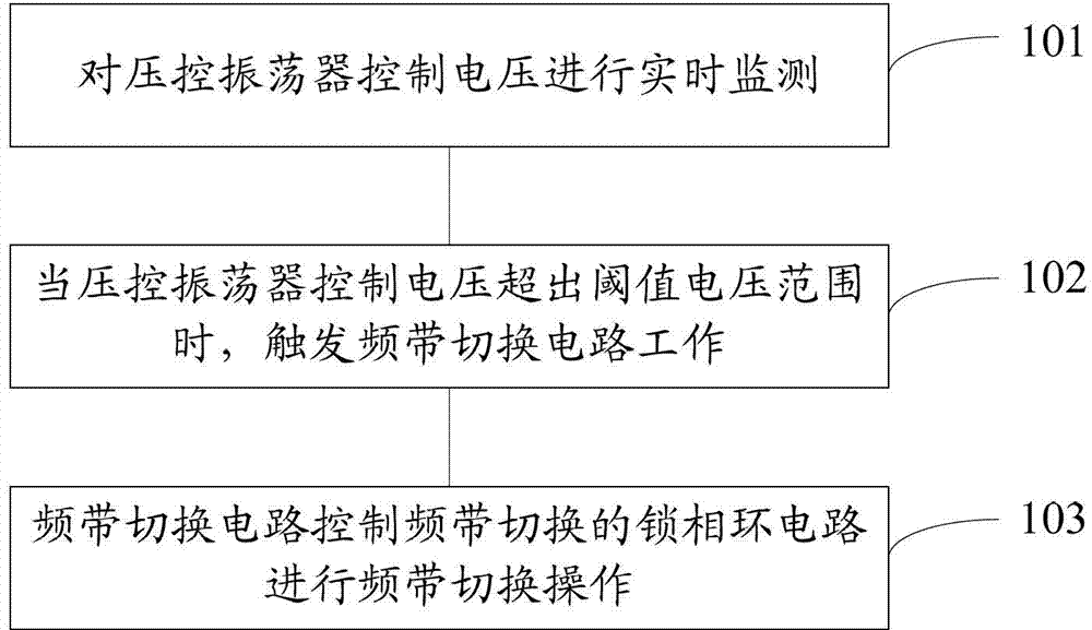
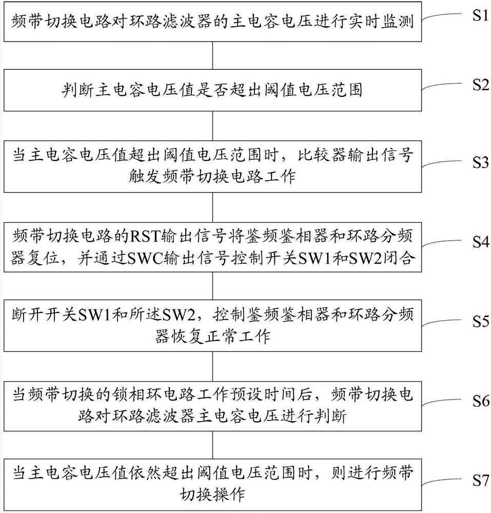
[0031] The invention discloses a method for fast frequency band switching of a phase-locked loop. The phase-locked loop circuit for frequency band switching is adopted. The method includes: monitoring the control voltage of a voltage-controlled oscillator in real time; When within the range, the frequency band switching circuit is triggered to work; the frequency band switching circuit controls the phase-locked loop circuit of the frequency band switching to pe...


PUM


Abstract

The invention discloses a phase-locked loop rapid frequency band switching method. According to the method, a phase-locked loop circuit with a frequency band switching function is adopted. The method comprises the following steps of performing real-time monitoring on the control voltage of a voltage control oscillator; when the control voltage of the voltage control oscillator goes beyond the threshold voltage range, triggering a frequency band switching circuit to work; controlling the phase-locked loop circuit with the frequency band switching function to perform frequency band switching operation by virtue of the frequency band switching circuit. According to the phase-locked loop rapid frequency band switching method disclosed by the invention, a method of performing fixed-period collection, comparison and judgment on the control voltage of the voltage control oscillator is not adopted, real-time monitoring is performed on the control voltage of the voltage control oscillator, and when the control voltage of the voltage control oscillator goes beyond the threshold voltage range, the frequency band switching circuit is triggered to perform frequency band switching operation, so that the problem of wrong frequency band switching of the phase-locked loop circuit during underdamping is solved; in addition, a method of triggering delay judgment after real-time sampling comparison is adopted, so that the delay judgment time and the frequency band switching time are reduced to the greatest extent. The invention further discloses the phase-locked loop circuit with the frequency band switching function.

Description

technical field [0001] The present invention relates to the technical field of radio frequency circuit and wireless communication, more specifically, relates to a phase-locked loop fast frequency band switching method and a phase-locked loop circuit for frequency band switching. Background technique [0002] At present, the phase-locked loop frequency synthesizer is one of the core module circuits in today's wireless communication systems. The operating frequency range and locking time are two important indicators to measure the performance of the phase-locked loop. Modern communication technology requires the phase-locked loop to have more and more The wider the operating frequency range, the engineering generally uses multiple sub-bands with overlapping frequency ranges to broaden the frequency range. [0003] Generally, a phase-locked loop needs to use a frequency band switching circuit to switch the frequency operating point from a certain sub-band to another sub-band. ...

Claims


Application Information

Patent Timeline
Patent Type & Authority Applications(China)
IPC IPC(8): H03L7/099H03L7/18
Inventor 阴亚东牟荣增阎跃鹏
Owner KUNSHAN BRANCH INST OF MICROELECTRONICS OF CHINESE ACADEMY OF SCI
Why Eureka
Try Eureka