Positional accuracy testing method of space manipulator in thermal vacuum tank

A space manipulator, precision testing technology, applied in the direction of measuring devices, electrical devices, instruments, etc., can solve the problem of low precision test of space manipulator

Inactive Publication Date: 2013-11-27
HARBIN INST OF TECH
View PDF5 Cites 2 Cited by
  • Summary
  • Abstract
  • Description
  • Claims
  • Application Information

AI Technical Summary

Problems solved by technology

[0004] In order to solve the problem that the position accuracy test of the space manipulator in the thermal vacuum tank is not high in the prior art, the present invention further provides a method for testing the position accuracy of the space manipulator in the thermal vacuum tank

Method used


Image

  • Positional accuracy testing method of space manipulator in thermal vacuum tank
  • Positional accuracy testing method of space manipulator in thermal vacuum tank
  • Positional accuracy testing method of space manipulator in thermal vacuum tank

Examples


specific Embodiment approach 1

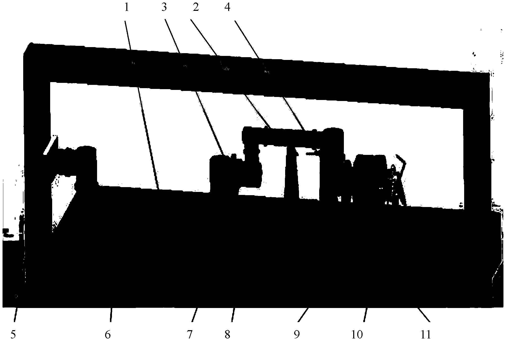
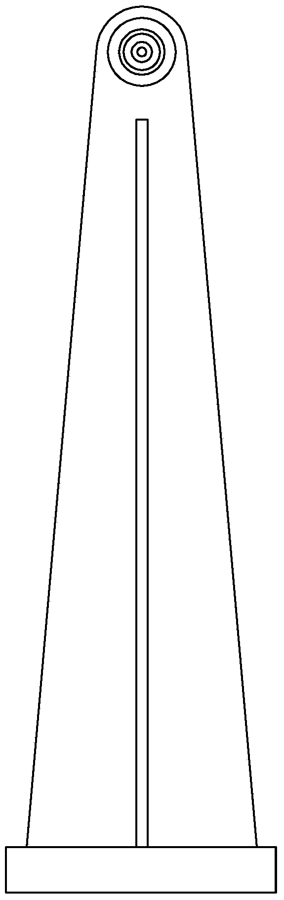
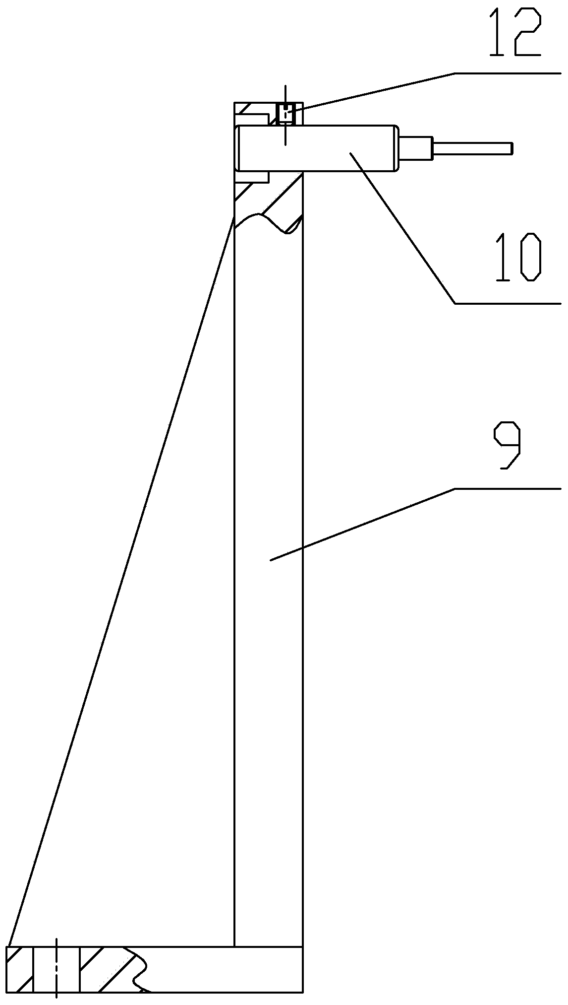
[0014] Specific implementation mode one: as Figures 1 to 3 As shown, a method for testing the position accuracy of a space manipulator in a thermal vacuum tank described in this embodiment is based on including a thermal vacuum tank and a mechanical arm mounting frame 5 located in the thermal vacuum tank, a steel plate 11, a roller 8, and a support frame 7 , guided rebound type LVDT displacement sensor 10 and the test system of the sensor fixing frame 9, the mechanical arm mounting frame 5 is fixedly connected to the steel plate 11, and the space manipulator 6 is placed on the steel plate 11 and is located in the mechanical arm mounting frame 5 , the base (root) flange of the space manipulator 6 is fixed on the inner wall of the corresponding side column of the manipulator mounting frame 5, and the space manipulator 6 is composed of the first arm 1, the first arm connected in sequence from the base end to the end The joint 3, the second arm bar 2 and the second joint 4 are fo...

specific Embodiment approach 2

[0019] Specific embodiment two: The LVDT displacement sensor 10 described in this embodiment is a guided rebound type LVDT displacement sensor with a relative accuracy of 0.05%, a resolution of 0.001 μm, an elastic force of less than 0.2N, and a temperature adaptable range of -40°C to 150°C. ℃. Other components and connections are the same as those in the first embodiment.

specific Embodiment approach 3

[0020] Specific implementation mode three: as Figures 1 to 3 As shown, the guided springback LVDT displacement sensor described in this embodiment has a relative accuracy of 0.05%, a resolution of 0.001 μm, an elastic force of less than 0.2N, and a temperature adaptable range of -40°C to 150°C. Other components and connections are the same as those in the second embodiment.


PUM


Abstract

The invention discloses a positional accuracy testing method of a space manipulator in a thermal vacuum tank, and relates to the field of positional accuracy testing of space manipulators. The problem that the testing accuracy of the position of the space manipulator in the thermal vacuum tank is not high in the prior art can be solved. The positional accuracy testing method is characterized in that two tail end positions are chosen for the space manipulator, and two LVDT displacement sensors are arranged at each position in a square crossing mode; the initial displacement of the LVDT displacement sensors is guaranteed to be larger than the positional accuracy of the tested space manipulator so that the space manipulator can make contact with all the LVDT displacement sensors during reciprocating motion; the space manipulator is made to make plane motion on a steel plate in the states of normal temperature, high temperature and low temperature, and the space manipulator is controlled to make reciprocating motion at the two tail end positions; the measured value of the LVDT displacement sensors is obtained; with the normal temperature positional accuracy being the reference, and the positional accuracy in the X direction and the Y direction of the space manipulator under the high temperature environment and the low temperature environment is obtained. The positional accuracy testing method is used for conducting positional accuracy testing on the space manipulator in the thermal vacuum tank.

Description

technical field [0001] The invention relates to a position accuracy test method in a thermal vacuum tank of a space manipulator, and relates to the field of position accuracy test of a space manipulator. Background technique [0002] With the advancement of technology, human activities are constantly expanding into space. Countries are studying the space robot arm on-orbit service technology for the purpose of satellite maintenance, life extension and space junk removal by means of space robots. However, affected by the gravity of the ground and the test environment, the ground test of the space manipulator has always been a key issue that plagues the development of the manipulator. It is mainly manifested in: 1) The space manipulator is designed for the environment of microgravity on orbit in space. Without auxiliary test equipment, its joint driving torque is not enough to overcome the gravity moment, and it cannot realize arbitrary joint linkage. The planned path reaches...

Claims


Application Information

Patent Timeline
Patent Type & Authority Applications(China)
IPC IPC(8): G01B7/00
Inventor 刘宇蒋再男刘宏徐文福
Owner HARBIN INST OF TECH
Why Eureka
Try Eureka