Current reference circuit

A current reference and reference current technology, applied in the direction of adjusting electrical variables, control/regulation systems, instruments, etc., can solve the problems of collector voltage deviation, current mirror current mismatch, and inability to accurately offset, so as to achieve accurate voltage equalization and increase Good effect of PSRR and temperature coefficient

Inactive Publication Date: 2015-06-17
UNIV OF ELECTRONICS SCI & TECH OF CHINA
View PDF4 Cites 0 Cited by
  • Summary
  • Abstract
  • Description
  • Claims
  • Application Information

AI Technical Summary

Problems solved by technology

figure 2 It is the output waveform of the circuit. It can be seen that the waveform of Iref is a curve. Since the temperature coefficient of the current with a positive temperature coefficient and the current with a negative temperature coefficient also change with the temperature, it cannot be precisely offset
[0005] The disadvantages of this circuit are: 1. Current mirror current mismatch problem: Due to the channel modulation effect, the drain-source voltages of PMOS current mirrors M1, M2, and NMOS current mirrors M3, M4 are not completely equal, resulting in the collection of transistors Qa, Qb The electrode voltage is skewed, which in turn causes the output current reference to be not very accurate
2. Due to the use of a basic dual-tube current mirror, the PSRR (power supply rejection ratio) of this current reference circuit is not very good
3. Since the circuit is relatively simple and no high-order compensation is used, the temperature coefficient of the output current reference is not very high

Method used


Image

  • Current reference circuit
  • Current reference circuit
  • Current reference circuit

Examples


Embodiment Construction

[0026] Below in conjunction with accompanying drawing, describe technical scheme of the present invention in detail:

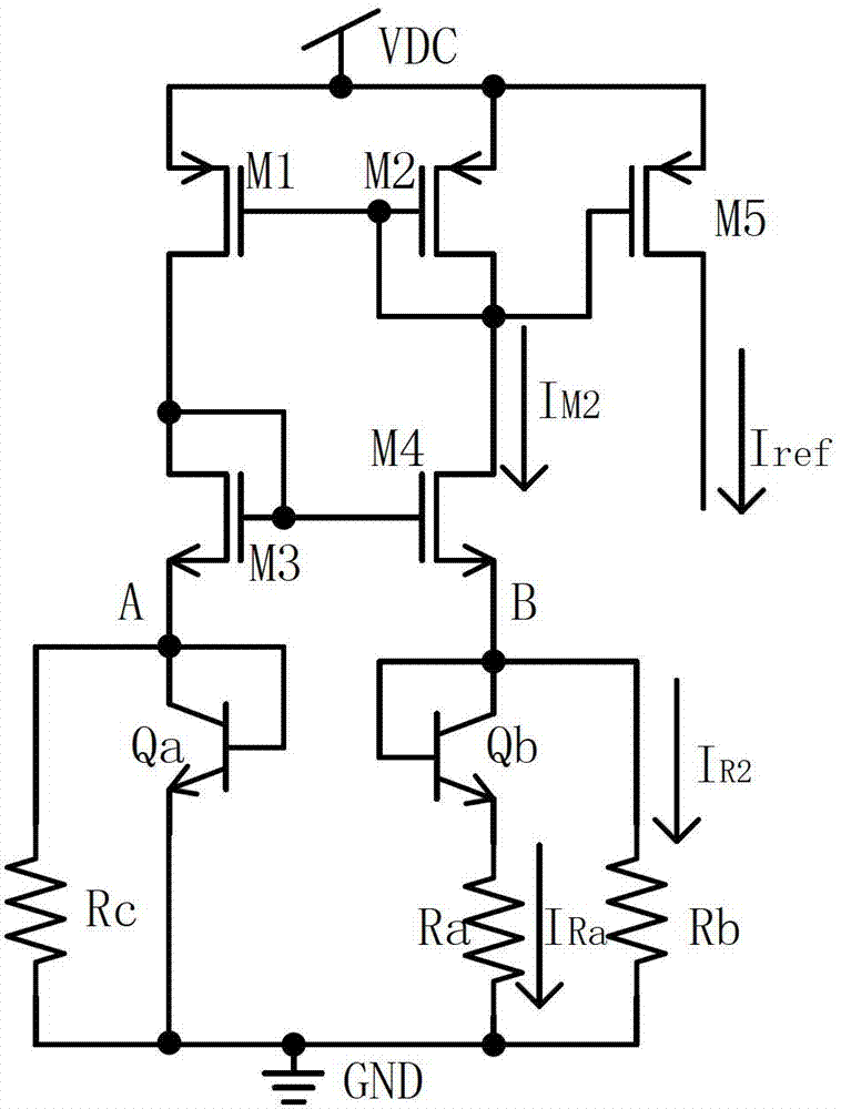
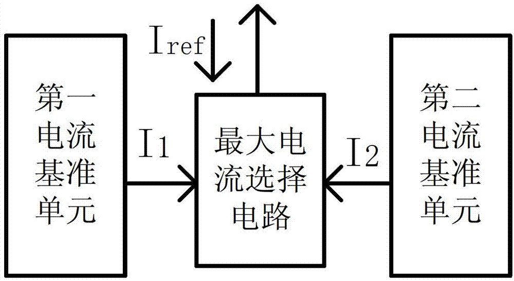
[0027] Such as image 3 As shown, a current reference circuit proposed by the present invention includes a first current reference unit, a second current reference unit and a maximum current selection circuit, and the output end of the first current reference unit is connected to the first current selection circuit of the maximum current selection circuit. The input terminal is connected, the output terminal of the second current reference unit is connected to the second input terminal of the maximum current selection circuit, and the output terminal of the maximum current selection circuit is the output terminal of the current reference circuit; wherein,

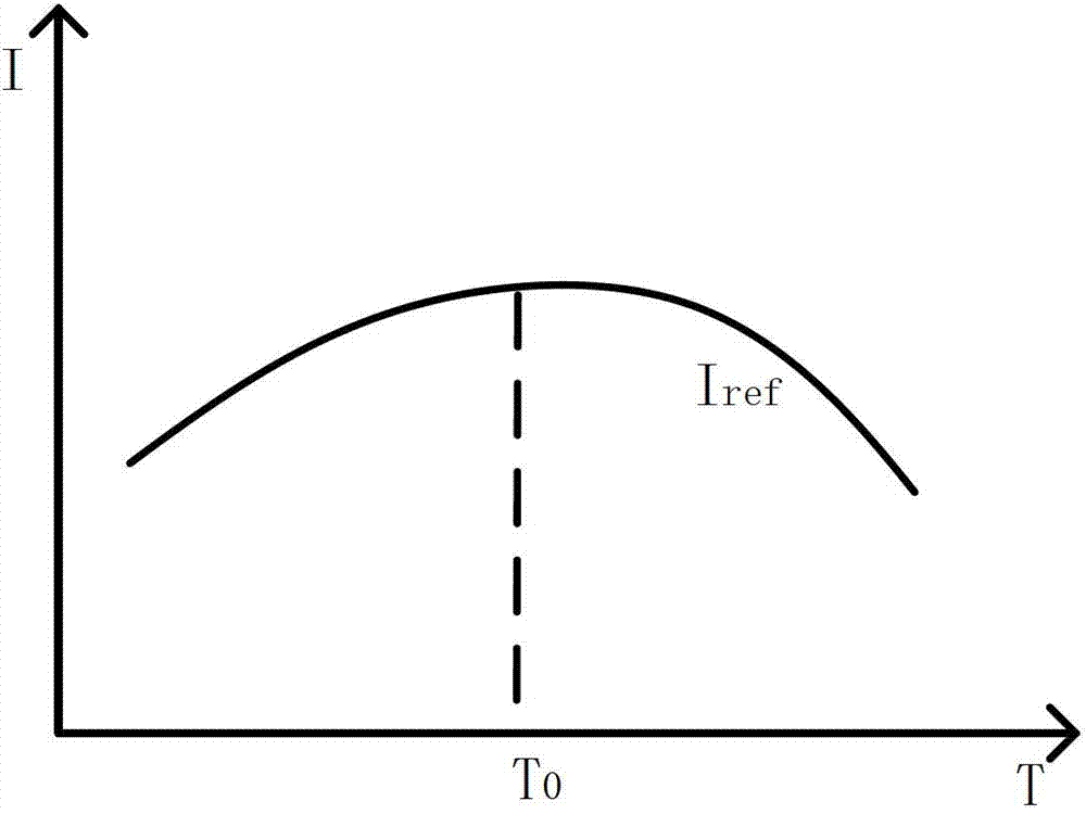
[0028] The first current reference unit and the second current reference unit are used to generate an independent reference current output respectively, and the reference current generated by the first curr...


PUM


Abstract

The invention relates to the technique of integrated circuits, in particular to a current reference circuit. The current reference circuit is characterized by comprising a first current reference unit, a second current reference unit and a maximum current selecting circuit, wherein the output end of the first current reference unit is connected with the first input end of the maximum current selecting circuit, the output end of the second current reference unit is connected with the second input end of the maximum current selecting circuit, and the output end of the maximum current selecting circuit is the output end of the current reference circuit. The current reference circuit has the advantages that by adopting a cascode current mirror, currents are copied more accurately, collector electrode voltage of an audion Q1 and collector electrode voltage of an audion Q2 are accurate and equal, the PSRR is improved, the current in the first current reference unit and the current in the second current reference unit are selected by adopting the maximum current selecting circuit, and therefore the temperature coefficient of the output currents is better. The current reference circuit is particularly suitable for current reference circuits.

Description

technical field [0001] The invention relates to integrated circuit technology, in particular to a current reference circuit. Background technique [0002] In integrated circuits, reference sources are widely used, including voltage reference sources and current reference sources. With the development of integrated circuit technology, the performance requirements of the chip are getting higher and higher, and the accuracy of the current provided by the current reference circuit is also getting higher and higher. [0003] At present, there are two types of circuits that can provide accurate current reference sources: the first is to design a high-precision voltage reference circuit inside the chip to generate a reference voltage that has nothing to do with temperature, process, and power supply voltage, and then through additional circuits Convert the reference voltage into a reference current; the second is to directly add a current with a negative temperature coefficient an...

Claims


Application Information

Patent Timeline
Patent Type & Authority Patents(China)
IPC IPC(8): G05F1/56
Inventor 方健潘华彭宜建王贺龙程春云李源
Owner UNIV OF ELECTRONICS SCI & TECH OF CHINA
Why Eureka
Try Eureka