Wood carving assembly and a method for making the same

a wood carving and assembly technology, applied in the field of wood carving assembly, can solve the problems of inability to make relatively fast and accurate duplicates of objects, inability to use manual and motorized cutting tools, inability to accurately duplicate objects, etc., to achieve accurate duplicates, increase rigidity and accuracy, and increase the effect of accuracy

Inactive Publication Date: 2007-10-16
COLEMAN HARRISON L +1
View PDF17 Cites 12 Cited by
  • Summary
  • Abstract
  • Description
  • Claims
  • Application Information

AI Technical Summary

Benefits of technology

[0006]It is a first non-limiting advantage of the present invention to provide a wood carving assembly which overcomes some or all of the previously delineated disadvantages of prior wood carving assemblies.
[0007]It is a second non-limiting advantage of the present invention to provide a method for making a wood carving assembly which produces a wood carving assembly which overcomes some or all of the previously delineated disadvantages of prior wood carving assemblies.
[0008]It is a third non-limiting advantage of the present invention to provide a carving assembly for duplicating a form having a certain shape. Particularly, the provided wood caring assembly includes a frame assembly having a pair of substantially parallel and horizontal first rails, a second rail which is perpendicular to the pair of first rails, a pair of vertical support members each including at least one first linear bearing, wherein a unique one of the first rails is slidably disposed within each of the linear bearings, and wherein the second rail is disposed between the pair of vertical support members; a carriage assembly having a tubular member containing at least one second linear bearing and a first substantially flat mounting surface which is pivotally coupled to the tubular member, wherein the second rail is slidably disposed within the at least one second linear bearing; a handle member having a handle portion and a stylus portion, wherein the handle member is coupled to and orthogonally projects from the mounting surface and wherein the handle portion and the stylus portion extend from the handle member in substantially opposite vertical directions; a tool holder member which includes a collar portion which is adapted to selectively receive a conventional cutting tool, wherein the tool holder member is coupled to and orthogonally projects from the mounting surface, and a chain assembly which allows the form to be accurately duplicated.
[0009]It is a fourth non-limiting advantage of the present invention to provide a carving assembly. Particularly, the carving assembly comprises a pair of generally cylindrical and parallel X-axis rails; a pair of substantially vertical members which are slidably disposed upon the pair of X-axis rails, wherein the vertical members have a plurality of equally spaced and aligned apertures; a lead screw assembly which is selectively coupled to a unique one of the pair of vertical members, effective to increase the rigidity and accuracy along the X-axis rails; a generally cylindrical Y-axis rail which is selectively disposed within a unique pair of the aligned apertures; a movable carriage assembly which is slidably disposed upon the Y-axis rail, the carriage assembly having a pair of flanges orthogonally projecting therefrom; a mounting member which is pivotally coupled to the pair of flanges, and a chain assembly which allows a form to be accurately duplicated.
[0010]It is a fifth non limiting advantage of the present invention to provide a method for duplicating a shape of an object. The method includes duplicating a shape of a an object, the method comprising the steps of:
[0011]providing a frame assembly having a pair of horizontal and parallel first rails, a pair of vertical support members which are slidably disposed upon the pair of rails, and a horizontal second rail which is disposed orthogonal to the first rails;

Problems solved by technology

Particularly, the manual and motorized cutting tools do not enable an individual to make relatively fast and accurate duplicates of an object.
This type of duplication technique is inherently inaccurate and time consuming as it depends almost entirely upon the artistic skill of the individual.
Namely, these machining centers are oftentimes very expensive, have a relatively large “footprint”, and require formalized training in the programming language utilized by the computer controller.
Additionally, these computer controlled machining centers may be able to accurately duplicate objects which are originally produced by that machine (i.e., the “original” object sought to duplicated was also carved by that computer controlled machine), but are unable to accurately duplicate objects which were not produced by that machine.

Method used


Image

  • Wood carving assembly and a method for making the same
  • Wood carving assembly and a method for making the same
  • Wood carving assembly and a method for making the same

Examples


Embodiment Construction

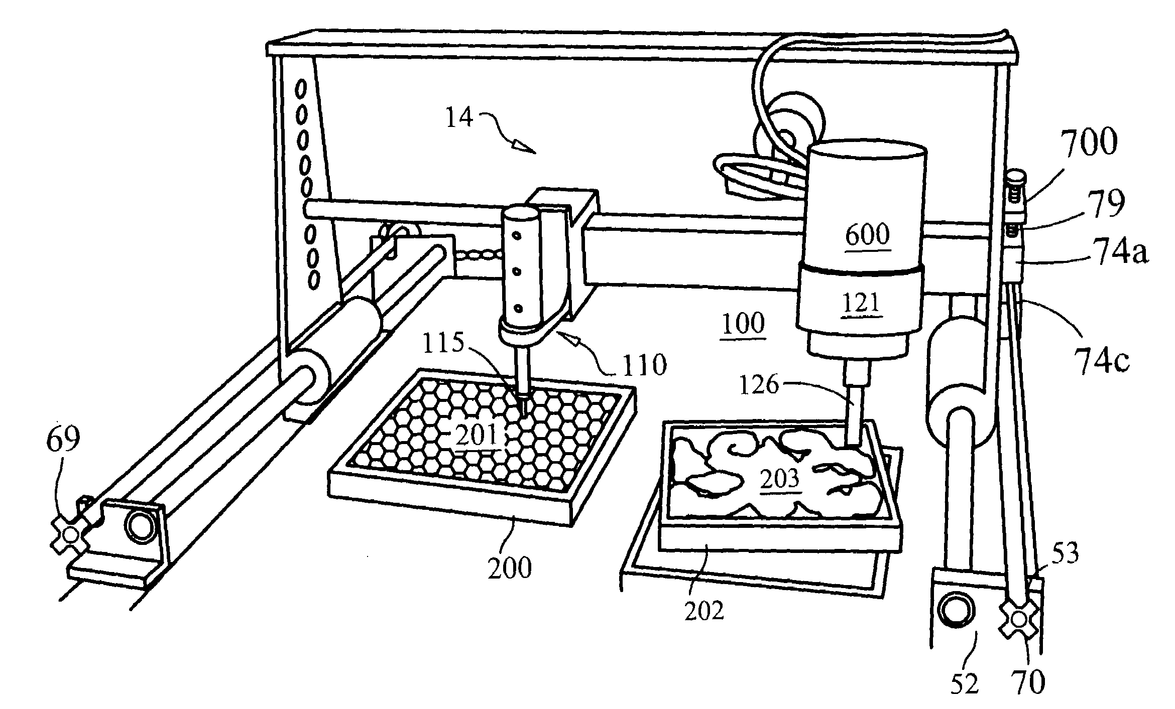
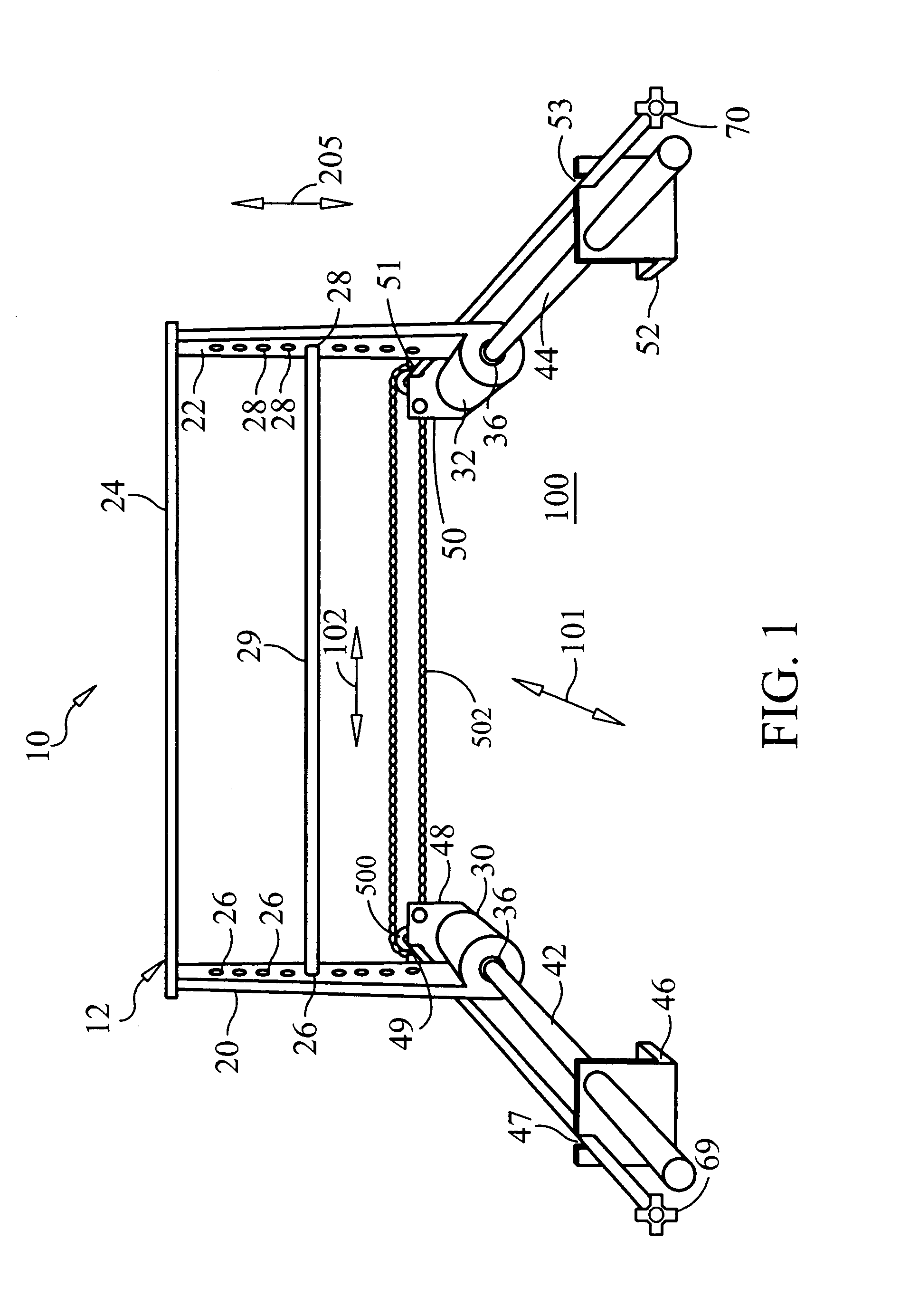
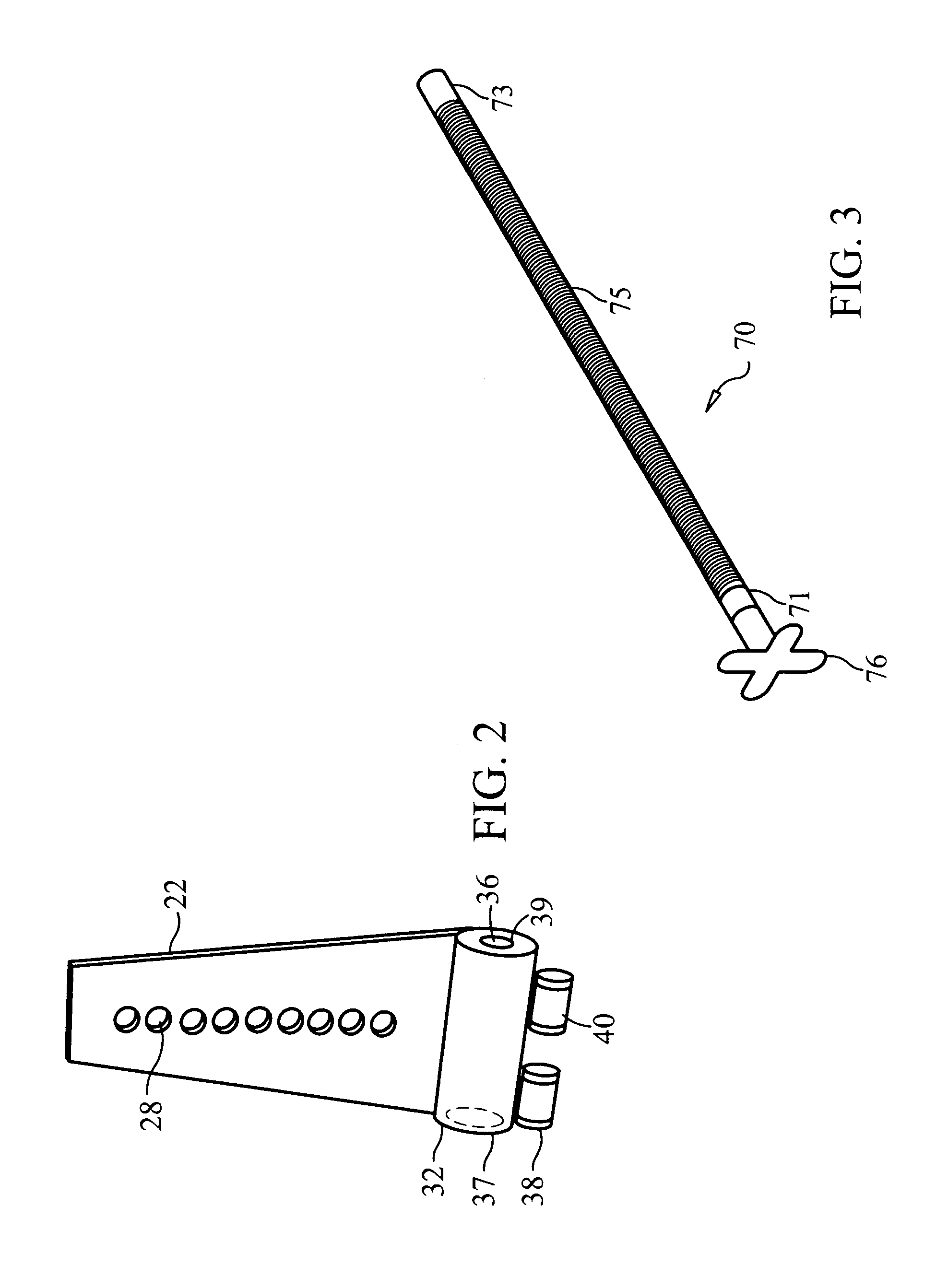
[0024]As best shown in FIGS. 1-7, a carving assembly 10 is provided and is made in accordance with the teachings of the preferred embodiment of the invention. Assembly 10 is generally comprised of a frame assembly or a frame portion 12 and a tool carriage or tool head assembly portion or assembly 14. Frame portion 12 includes a pair of substantially vertical, identical, and generally “A”-shaped side members 20, 22. Members 20, 22 are coupled together by a substantially planar top member 24. Each member 20, 22 has a plurality of respective apertures 26, 28 which are vertically and equally and alignably spaced upon the respective members 20, 22. As shown, members 20, 22 are oriented and coupled together by a top member 24 in a manner which causes each aperture 26 of member 20 to be substantially aligned with (e.g., on the same horizontal axis with) a unique one of the respective apertures 28 of member 22. Frame members 20, 22, 24 are made, in one non-limiting embodiment, from a relati...


PUM

PropertyMeasurementUnit
shapeaaaaaaaaaa
movementaaaaaaaaaa
time consumingaaaaaaaaaa

Abstract

A carving assembly 10 for use in duplicating a blank or form. The carving assembly 10 includes stylus 112 and a tool holder 120 which are coupled together using a slidable carriage 14 to allow any movement of the stylus to cause a cutting tool 121 mounted in the tool holder 120 to move in the exact same manner. Carriage 14 is mounted upon a frame, assembly which permits sliding motion in two orthogonal directions 101, 102.

Description

FIELD OF THE INVENTION[0001]The present invention generally relates to a wood carving assembly and to a method for making or constructing a wood carving assembly and more particularly, to a wood carving assembly which is adapted to accurately and selectively duplicate an object.BACKGROUND OF THE INVENTION[0002]Wood carving entails the application or use of a cutting tool to a block of wood material to remove portions of the wood in order to shape that wood block into a desired configuration or design. Traditionally, these cutting tools are conventional hand tools such as chisels and saws which are used by an individual to manually remove portions of a piece of wood in order to shape this piece in any manner the individual desires. These hand tools have been supplemented with automated or motorized cutting tools, such as electric routers and sanders, which reduce the amount of physical work necessary to shape to wood. Further, computer controlled cutting machines are available which ...

Claims


Application Information

Patent Timeline
Patent Type & Authority Patents(United States)
IPC IPC(8): B23C1/16
CPCB23Q35/10B27C5/003B44B3/001B44B3/02B44B3/006Y10T409/301232Y10T409/30252
Inventor COLEMAN, HARRISON L.COLEMAN, GERALD E.
Owner COLEMAN HARRISON L
Why Eureka
Try Eureka