A multi -channel rotation joint

A rotary joint, multi-channel technology, applied in the direction of pipe components, etc., can solve the problems of unfavorable installation and maintenance, low sealable pressure, heavy weight, etc., and achieve the effect of easy maintenance and maintenance, compact and reasonable structure, and reduced difficulty.

Active Publication Date: 2016-08-10
BC P INC CHINA NAT PETROLEUM CORP +2
View PDF8 Cites 0 Cited by
  • Summary
  • Abstract
  • Description
  • Claims
  • Application Information

AI Technical Summary

Problems solved by technology

The single-channel rotary joint can only meet the connection control of a single hydraulic hose, but cannot meet the requirements of the overall design of the coiled tubing equipment and the overall layout of the equipment. There is an urgent need for a multi-channel rotatable joint that can achieve dynamic and static high-pressure sealing conditions. Connection joints to realize simultaneous connection of multiple hydraulic lines on one hose drum
[0003] The solution to similar situations at home and abroad is to design multiple rotary joints with fewer channels; moreover, the multi-channel rotary joints of the previous hose drums with similar functions are large, heavy, and have low sealable pressure, which is not conducive to installation and maintenance. , has been unable to meet the demand for higher fluid delivery; and increases the volume of the matching hose drum, which is not conducive to the compact design of the hose drum

Method used


Image

  • A multi -channel rotation joint
  • A multi -channel rotation joint
  • A multi -channel rotation joint

Examples


Embodiment Construction

[0024] In order to make the object, technical solution and advantages of the present invention clearer, the implementation manner of the present invention will be further described in detail below in conjunction with the accompanying drawings.

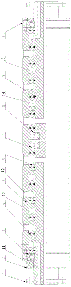
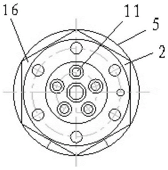
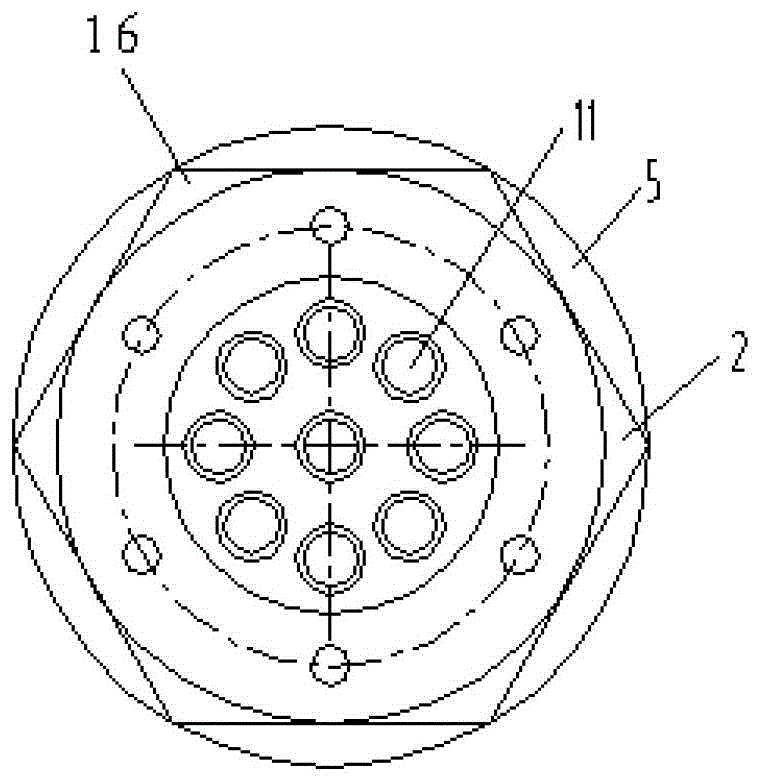
[0025] Such as figure 1 and figure 2 As shown, the present invention provides a multi-channel rotary joint, including a rotary housing 5 and a fixed shaft 9, the fixed shaft 9 is arranged in the rotary housing 5, and the two form a rotary sealed connection, and the rotary housing 5 is provided with The driving device 16 can drive the rotating housing 5 to perform a rotating movement, and a multi-channel through hole 11 is formed along the axial direction of the fixed shaft 9. The outer surface of the fixed shaft 9 is provided with a plurality of annular liquid flow channels 13, and the rotating housing 5 is formed with a plurality of communication holes 12 that communicate with a plurality of annular liquid flow channels 13 in one-to...


PUM


Abstract

The invention discloses a multichannel rotary connector and belongs to the field of continuous tubing operating machines. The multichannel rotary connector comprises a rotary casing and a fixed shaft, wherein the fixed shaft is arranged in the rotary casing, and the fixed shaft and the rotary casing form rotary dynamic seal connection. A driving device is arranged on the rotary casing, multichannel through holes are formed in the axial direction of the fixed shaft, a plurality of annular liquid flowing hole channels are arranged on the excircle surface of the fixed shaft, a plurality of communication holes in one-to-one correspondence to the plurality of annular liquid flowing hole channels are formed in the rotary casing, sealing is performed among the annular liquid flowing hole channels, and the multichannel through holes and the plurality of annular liquid flowing hole channels are communicated in one-to-one correspondence. According to the multichannel rotary connector, the multichannel through holes are formed in the axial direction of the fixed shaft, the plurality of communication holes are formed in the rotary casing, the multichannel through holes and the plurality of communication holes are communicated in one-to-one correspondence, and a plurality of sealing rings are arranged between the fixed shaft and the rotary casing to achieve sealing. Therefore, sealing capability of the multichannel rotary connector is improved, equipressure liquid and non-equipressure liquid can be conveyed simultaneously, and the multichannel rotary connector is compact in structure and convenient to maintain.

Description

technical field [0001] The invention relates to the field of coiled tubing operating machines, in particular to a multi-channel rotary joint. Background technique [0002] With the development of domestic coiled tubing technology and the need for coiled tubing equipment control, the number of hydraulically controlled hoses has also increased accordingly. The single-channel rotary joint can only meet the connection control of a single hydraulic hose, but cannot meet the requirements of the overall design of the coiled tubing equipment and the overall layout of the equipment. There is an urgent need for a multi-channel rotatable joint that can achieve dynamic and static high-pressure sealing conditions. Connect the joints to realize the simultaneous connection of multiple hydraulic lines on one hose drum. [0003] The solution to similar situations at home and abroad is to design multiple rotary joints with fewer channels; moreover, the multi-channel rotary joints of the prev...

Claims


Application Information

Patent Timeline
Patent Type & Authority Patents(China)
IPC IPC(8): F16L39/06
Inventor 宋治国刘寿军朱再思杨志敏
Owner BC P INC CHINA NAT PETROLEUM CORP
Why Eureka
Try Eureka