Cloud platform machine room dustproof heat cooling system

A technology of cooling system and cloud platform, applied in cooling/ventilation/heating transformation, electrical components, electrical equipment structural parts, etc., can solve problems such as position and quantity adjustment that cannot be dissipated

Active Publication Date: 2020-07-10
广州信溢创科技股份有限公司
View PDF4 Cites 0 Cited by
  • Summary
  • Abstract
  • Description
  • Claims
  • Application Information

AI Technical Summary

Problems solved by technology

The internal circulation of the computer room is coupled with the external circulation. When the outdoor air temperature is high, the temperature of the air required by the server is lowered by the external circulation first, and then lowered to the required nominal value by the precision air conditioner; In the lower case, the air required by the server directly passes through the external circulation to reach the required nominal value; the disadvantage of this invention is that the location and quantity of heat dissipation cannot be adjusted according to different usage requirements

Method used


Image

  • Cloud platform machine room dustproof heat cooling system
  • Cloud platform machine room dustproof heat cooling system
  • Cloud platform machine room dustproof heat cooling system

Examples


specific Embodiment approach 1

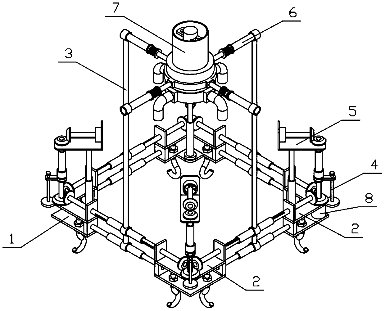
[0032] Combine below Figure 1-10Describe this embodiment, a dust-proof and heat-dissipating system for a cloud platform machine room, including a mounting bracket 1, a transmission bracket 2, a connecting bracket 3, an adjustment mechanism 4, a heat dissipation mechanism 5, a support bracket 6, an air outlet mechanism 7, and a drive motor 8. There are multiple mounting brackets 1, and connecting brackets 3 are threadedly connected between multiple mounting brackets 1, and transmission brackets 2 are fixedly connected to each mounting bracket 1, and multiple transmission brackets 2 are connected by connecting brackets. 3 transmission connection, each transmission bracket 2 is connected with an adjustment mechanism 4, each transmission bracket 2 is slidably connected with a heat dissipation mechanism 5, and the lower end of each heat dissipation mechanism 5 is fixedly connected to the corresponding installation bracket 1, each The adjustment mechanism 4 controls the transmissio...

specific Embodiment approach 2

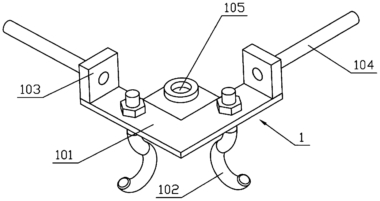
[0034] Combine below Figure 1-10 Describe this embodiment, this embodiment will further explain the first embodiment, the installation bracket 1 includes the installation base plate I101, the anchor bolts 102, the installation side plate 103, the sliding column 104 and the installation base plate II105, and the installation base plate I101 is connected with multiple Two anchor bolts 102 are fixedly connected with installation side plates 103 on both sides of the installation base plate I101, the two installation side plates 103 are fixedly connected with sliding columns 104, and the installation base plate I101 is fixedly connected with the installation base plate II105.

specific Embodiment approach 3

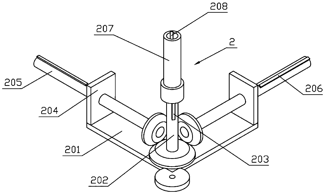
[0036] Combine below Figure 1-10 Describe this embodiment, this embodiment will further explain the second embodiment, the transmission bracket 2 includes a transmission bottom plate 201, a transmission shaft I 202, a connection key I 203, a transmission side plate 204, a transmission shaft II 205, a connection key II 206, and a transmission cylinder 207 and keyway I208, the transmission base plate 201 is rotatably connected to the transmission shaft I202, the transmission shaft I202 is fixedly connected to the connection key I203, both sides of the transmission base plate 201 are fixedly connected to the transmission side plate 204, and both transmission side plates 204 are rotated The transmission shaft II 205 is connected, the two transmission shafts II 205 are fixedly connected with the connection key II 206, the upper end of the transmission shaft I 202 is connected with the transmission cylinder 207 in rotation, the transmission cylinder 207 is provided with a keyway I 2...


PUM


Abstract

The invention relates to a heat dissipation system, in particular to a cloud platform machine room dustproof cooling system. The cooling device comprises mounting brackets, transmission brackets, connecting brackets, adjusting mechanisms, cooling mechanisms, a supporting bracket, an air outlet mechanism and a driving motor, the relative distance between the two corresponding mounting brackets canbe adjusted through the connecting brackets, so that the relative positions of the connecting brackets correspond to the positions, needing to be cooled, in the machine room, and the connecting brackets are fixedly connected to the ground after adjustment is completed; the connecting brackets can ensure that the two corresponding transmission brackets can be in transmission with each other; the driving motor drives one of the transmission brackets to move, the multiple transmission brackets can be in mutual transmission with each other, the transmission brackets drive the corresponding coolingmechanisms to move, the cooling mechanisms dissipate heat of the corresponding positions, and each adjusting mechanism controls the transmission state of the corresponding transmission brackets to the corresponding cooling mechanisms and adjusts the using number of the cooling mechanisms.

Description

technical field [0001] The invention relates to a heat dissipation system, more specifically a dust-proof and heat dissipation system for a computer room on a cloud platform. Background technique [0002] For example, the publication number CN105737298A is an energy-saving computer room cooling system, including a precision air conditioner, a plenum box, a return air device, a fully sensible heat exchanger, a cooling module, and an intelligent server cabinet. The heat dissipation system consists of a precision air conditioner, a static pressure box, an intelligent server cabinet, a return air device and a full sensible heat exchanger to form an internal circulation. The heat dissipation system consists of a fully sensible heat exchanger and a cooling module to form an external circulation. The internal circulation of the computer room is coupled with the external circulation. When the outdoor air temperature is high, the temperature of the air required by the server is lowe...

Claims


Application Information

Patent Timeline
Patent Type & Authority Applications(China)
IPC IPC(8): H05K7/20
CPCH05K7/20172H05K7/20145
Inventor 杨龙龙
Owner 广州信溢创科技股份有限公司
Why Eureka
Try Eureka