
Power unit coordination control system and method

A coordinated control system, coordinated control technology, applied in general control systems, control/regulation systems, adaptive control, etc., to ensure safety, speed up dynamic response, and avoid adverse effects.

Active Publication Date: 2013-12-04
大唐(北京)能源科技有限公司
View PDF6 Cites 5 Cited by
  • Summary
  • Abstract
  • Description
  • Claims
  • Application Information

AI Technical Summary

Problems solved by technology

[0005] The technical problem to be solved in this application is to provide a coordinated control system and method for generator sets to solve the fast response to the load demand of the power grid, ensure the safe and stable operation of the generator set during the rapid load change process, and suppress all power generation during the load change process. The problem of adverse effects of a disturbing factor

Method used


Image

  • Power unit coordination control system and method
  • Power unit coordination control system and method
  • Power unit coordination control system and method

Examples


Embodiment 1

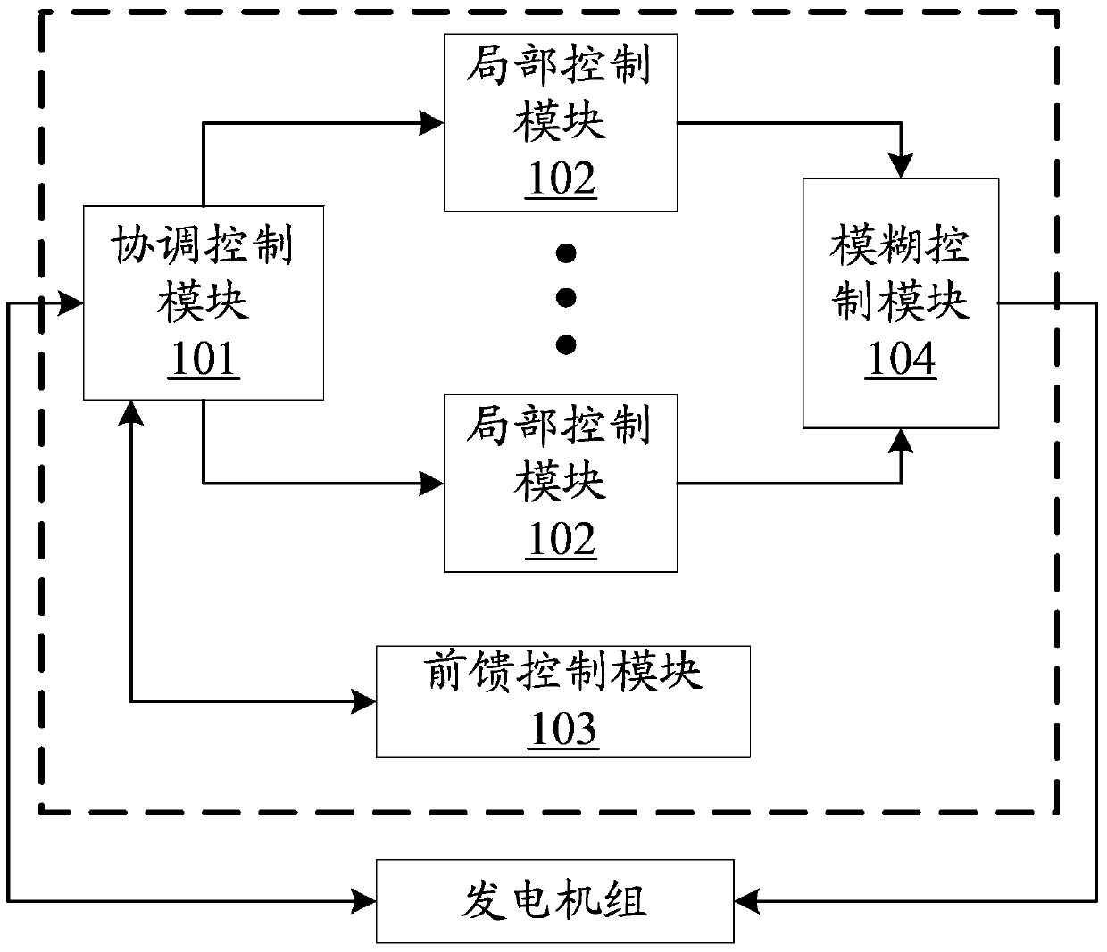
[0039] Such as figure 1 As shown, it is a coordinated control system for generator sets described in Embodiment 1 of the present application, which is characterized in that it includes: a coordinated control module 101, a plurality of local control modules 102, a feedforward control module 103 and a fuzzy control module 104; ,

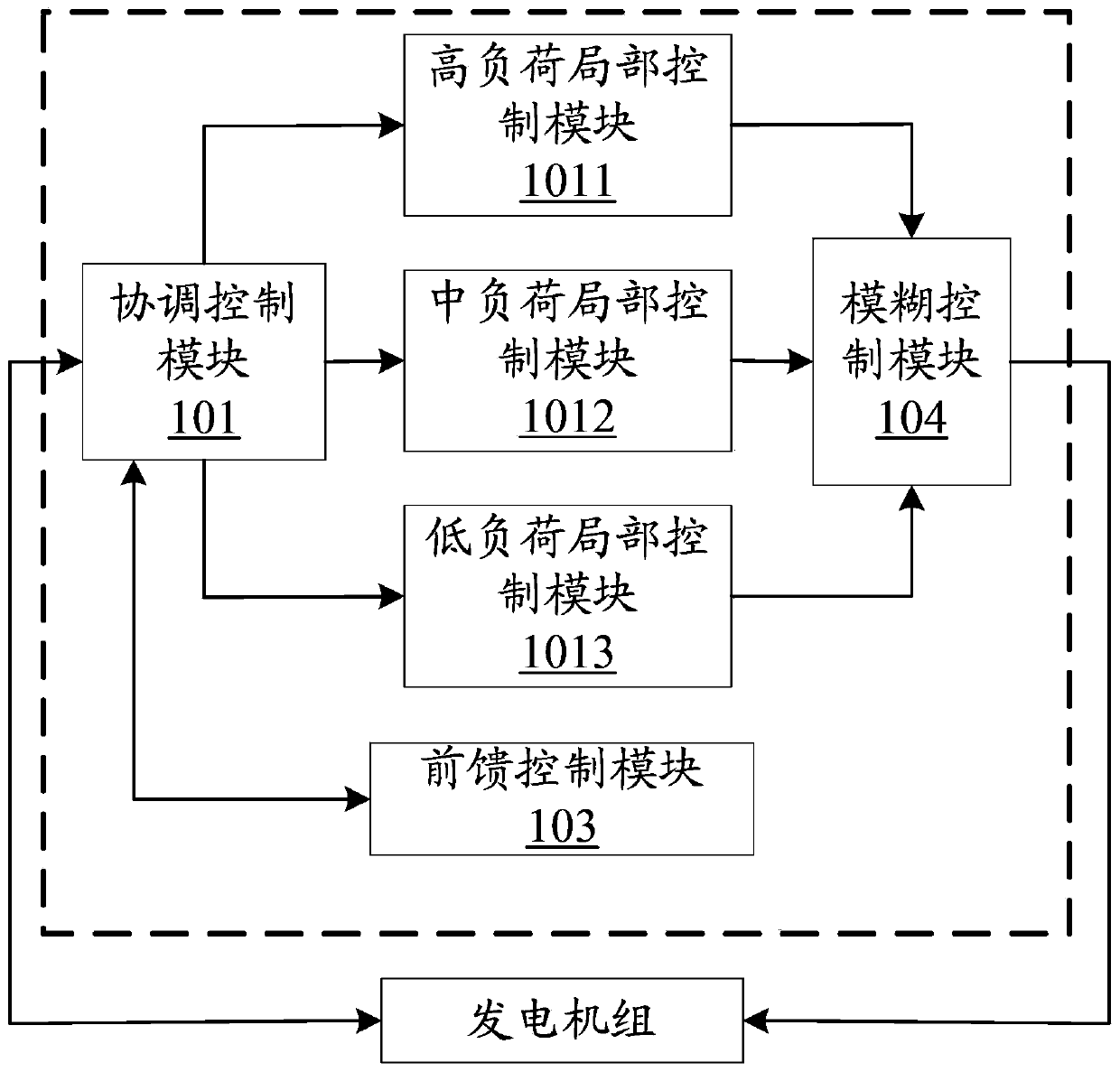
[0040] The coordinated control module 101 is respectively coupled with the plurality of local control modules 102, the feedforward control module 103 and the generator set, and is used to monitor the load of the generator set in real time, and according to the coordinated control module 101 The internal preset load segment standard value is compared with the monitored load to generate comparison result data, and the power, pressure given value and actual power of the generator set are calculated according to the comparison result data , the pressure value is sent to the local control module 102 corresponding to the different load segment intervals, an...

Embodiment 2

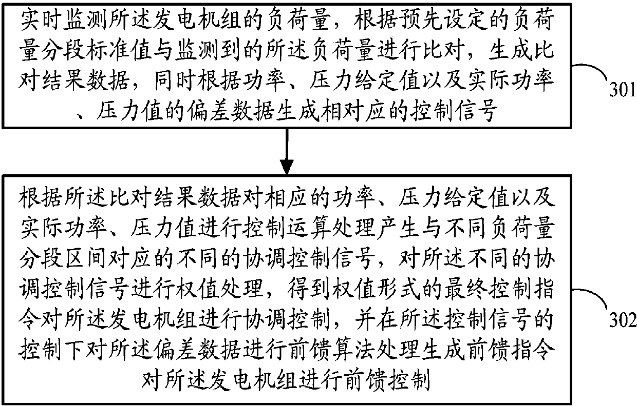
[0053] Such as image 3 As shown, it is a coordinated control method for generating sets described in Embodiment 2 of the present application, including:

[0054] Step 301, monitor the load of the generating set in real time, compare the load with the monitored load according to the preset standard value of the load, and generate the comparison result data, and at the same time, according to the power and pressure given values And the deviation data of actual power and pressure value generates corresponding control signals.

[0055] Step 302, according to the comparison result data, perform control operation processing on the corresponding power, pressure given value and actual power, pressure value to generate different coordinated control signals corresponding to different load intervals, and control the different Coordinated control signals are weight-processed to obtain final control commands in the form of weights for coordinated control of the generating sets, and under...


PUM


Abstract

The invention discloses a power unit coordination control system which comprises a coordination control module, a plurality of local control modules and a feedforward control module. The coordination control module is used for sending power, a pressure given value, pressure actual power, a pressure value of the power unit to the local control modules by comparing a load capacity segmented standard value with load capacity, and sending deviation data to the feedforward control module. The local control modules are used for generating coordination control signals and sending the coordination control signals to a fuzzy control module. The feedforward control module is used for performing feedforward algorithm processing on the deviation data to generate a feedforward instruction. The fuzzy control module is used for performing weight processing on the coordination control signals and outputting a final control instruction in a weight mode. By means of the power unit coordinated control system, quick response to needs of network load can be achieved, safe and stable operation of the power unit during load varying is ensured, and various interference factors are inhibited during the load varying.

Description

technical field [0001] The present application relates to the field of mechanical control, in particular to a coordinated control system and method for generating sets. Background technique [0002] The load demand of the power grid is greatly affected by factors such as industrial and agricultural production, social life, and climatic conditions. However, the above factors are highly random (for example: the temperature rises in summer, the load of air conditioners rises sharply, and the load on the power grid increases; passenger flow during the Spring Festival travel season The huge amount of electricity load in the transportation sector has increased sharply, the grid load has increased, etc.), and the problem of economic storage of large-capacity electric energy has not been effectively solved, which means that the generating set must not only have a certain capacity near the determined load point Good performance, but also to meet the needs of large-scale variable load...

Claims


Application Information

Patent Timeline
IPC IPC(8): G05B13/02
Inventor 邢红涛李少华周黎辉雷蕾叶翔
Owner 大唐(北京)能源科技有限公司
Learn More