Commodity driving structure

A technology for driving structures and goods, applied in the direction of coin-operated equipment for distributing discrete items, coin-operated equipment for distributing discrete items, coin-operated equipment for distributing discrete items, etc., which can solve problems such as inconvenience

Inactive Publication Date: 2013-12-04
HONG FU JIN PRECISION IND WUHAN CO LTD +1
View PDF5 Cites 2 Cited by
  • Summary
  • Abstract
  • Description
  • Claims
  • Application Information

AI Technical Summary

Problems solved by technology

In this way, when fixing each spring, it is necessary to forcefully clamp the said plastic element, and the spring can only be fixed in one direction, which is very inconvenient

Method used


Image

  • Commodity driving structure
  • Commodity driving structure
  • Commodity driving structure

Examples


Embodiment Construction

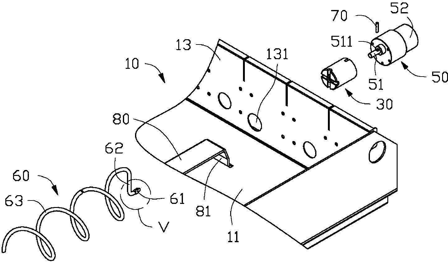
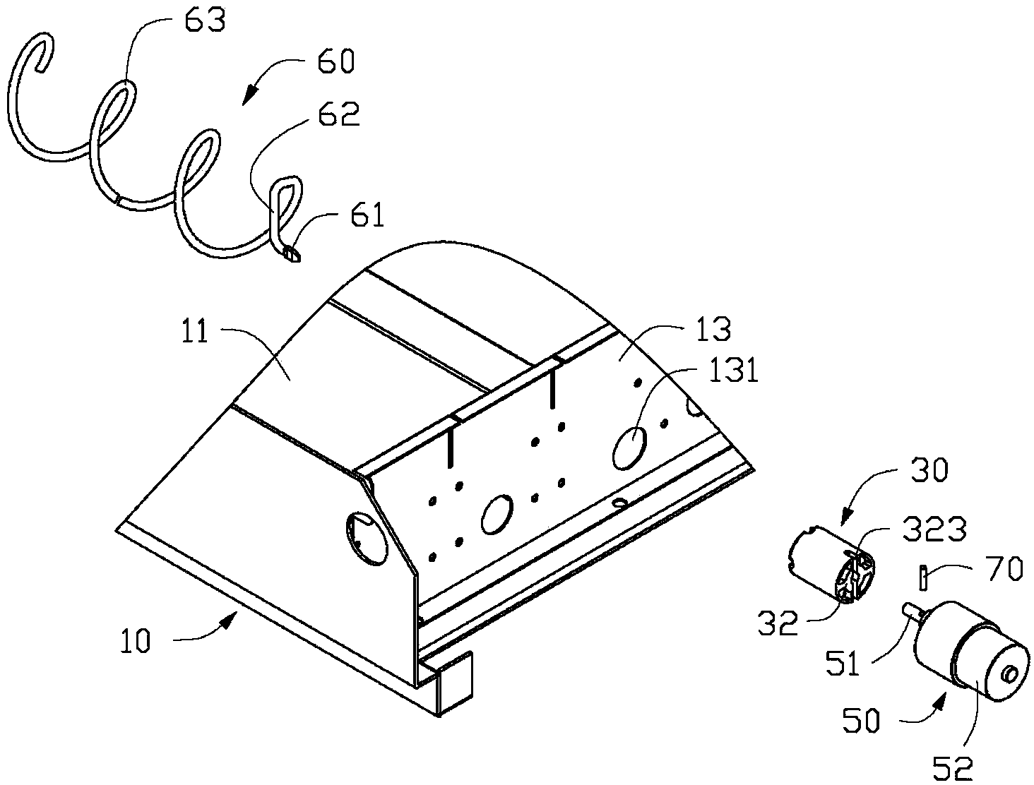
[0024] See figure 1 and figure 2 In a preferred embodiment of the present invention, a cargo driving structure includes a base 10, a fixing member 30, a driving member 50, and a pushing member 60. The cargo driving structure can push the cargo placed on the pushing member 60 out of the base 10 by rotating the pushing member 60.

[0025] The base 10 includes a bottom plate 11 and a side plate 13 perpendicular to the bottom plate 11. A supporting sheet 80 is installed on the bottom plate 11. The supporting sheet 80 is a long sheet body, and the supporting sheet 80 includes two fixed ends 81 (only one fixed end 81 is shown in the figure). The fixed end 81 is fixed on the bottom plate 11. The side plate 13 is provided with a receiving hole 131 for placing the driving member 50. In one embodiment, the stand 10 is a container on a vending machine.

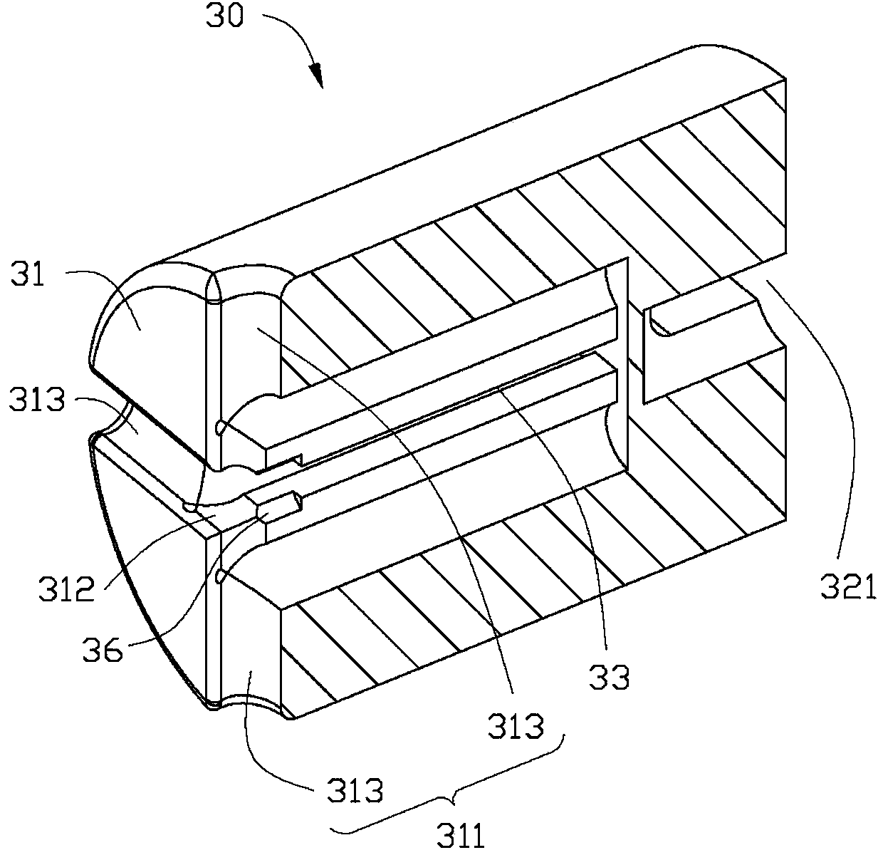
[0026] Please refer to image 3 and Figure 4 The fixing member 30 is a cylinder and includes a first side surface 31 and a second side...


PUM


Abstract

A dispensing device includes a rigid coil, a mounting member, and a motor. The rigid coil includes a helical portion, a proximal end, and a connecting portion connecting the proximal end to the helical portion. The helical portion includes a plurality of resilient spiral coils. Each adjacent two of the plurality of resilient spiral coils configured for clamping a product. The mounting member defines a latching slot and an inserting slot along an axial direction, and further defines a securing slot along a redial direction. The motor includes a rotating shaft. The proximal end is engaged in the latching slot. The connecting portion is engaged in the securing slot. The rotating shaft is inserted in the inserting slot. The rotating shaft is rotatable along the axial direction to rotate the rigid coil through the mounting member. The helical portion is rotatable to push the product out of a product channel.

Description

Technical field [0001] The invention relates to a goods driving structure, in particular to a goods driving structure used in an automatic vending machine. Background technique [0002] In some current vending machines, springs and motors are used as driving parts, and the springs are driven to rotate during the rotation of the motors to drive the goods in the containers off the shipping lane. Generally, vending machines have many layers of containers (usually 6 or more), and each layer has more than 8 cargo lanes. In this way, there are many springs and corresponding motors in a vending machine. At present, the spring and the motor are connected together through a shaft hole fitting, and are fixed by the elasticity of a plastic element. In this way, when fixing each spring, the plastic element needs to be clamped forcefully, and the spring can only be fixed in one direction, which is very inconvenient. Summary of the invention [0003] In view of the above, it is necessary to ...

Claims


Application Information

Patent Timeline
Patent Type & Authority Applications(China)
IPC IPC(8): G07F11/46
CPCG07F11/42
Inventor 陈允隆叶锦文周敦军
Owner HONG FU JIN PRECISION IND WUHAN CO LTD
Why Eureka
Try Eureka