Connectivity detection method, device and system
A technology for connectivity detection and target nodes, which is applied in the field of connectivity detection methods, devices and systems, can solve problems such as low efficiency, poor pertinence, and difficulty in identifying paths for source nodes, and achieve the effect of easy identification of paths
- Summary
- Abstract
- Description
- Claims
- Application Information
AI Technical Summary
Problems solved by technology
Method used
Image
Examples
Embodiment 1
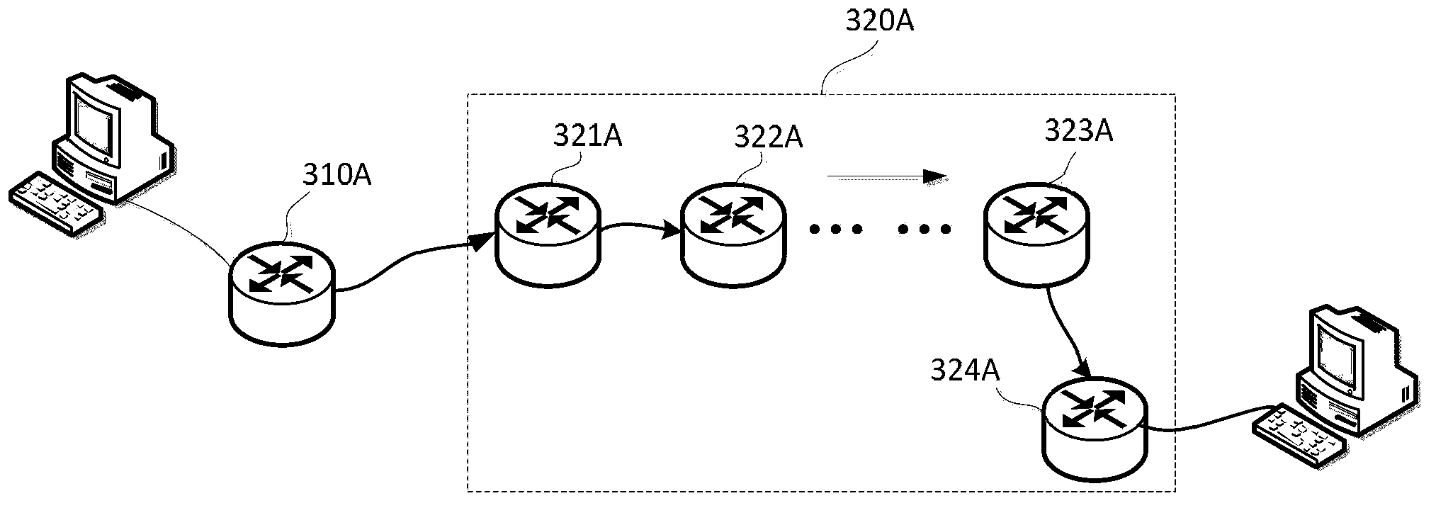
[0045] Figure 4 is a flow chart of the connectivity detection method provided in Embodiment 1 of the present invention, the connectivity detection method may be in Figure 3A In the non-source node routing bridge 320A, for example, it can be performed by any one of the non-source node routing bridge 321A, the non-source node routing bridge 322A...the non-source node routing bridge 323A and the non-source node routing bridge 324A. ; Of course, the connectivity detection method can also be in Figure 3B In the non-source node routing bridge 320B, for example, it can be performed by any one of non-source node routing bridge 321B, non-source node routing bridge 322B...non-source node routing bridge 323B and non-source node routing bridge 324B . Connectivity detection methods include:
[0046] Step 410, receiving connectivity detection request information, the connectivity detection request information includes source node identifier, multicast distribution tree identifier, tar...
Embodiment 2
[0056] Figure 5 is a flow chart of the connectivity detection method provided in Embodiment 2 of the present invention, and the connectivity detection method is in Figure 3A In the non-source node routing bridge 320A, for example, it can be performed by any one of the non-source node routing bridge 321A, the non-source node routing bridge 322A...the non-source node routing bridge 323A and the non-source node routing bridge 324A. Connectivity detection request information processing. Connectivity detection methods include:
[0057] Step 510, receiving connectivity detection request information.
[0058] The connectivity detection request information includes the identifier of the source node, the identifier of the multicast distribution tree, the identifier of the target node and the hop count.
[0059] Usually, the connectivity detection request information is sent by the source node routing bridge 310A (that is, the source node), where the identifier of the source node i...
Embodiment 3
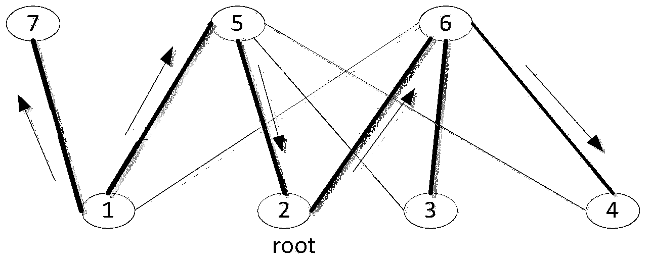
[0083] Figure 7 It is a schematic diagram of testing the multicast path through traceroute provided by Embodiment 3 of the present invention. The routing bridge RB1-RB7 are shown in the figure, and the tree formed by connecting the routing bridges with thick lines is the multicast distribution tree tree2. The bridge RB2 is the root of the multicast distribution tree, and now the routing bridge RB1 is used as the source node (that is, the corresponding Figure 3A In the source node routing bridge 310A), routing bridge RB5 and routing bridge RB4 are used as target nodes (that is, the corresponding Figure 3A In the non-source node routing bridge 324A), the connectivity detection from the source node RB1 to the target nodes RB4 and RB5 is performed, and the specific process is as follows:
[0084] Step A, the source node routing bridge RB1 generates a connectivity detection request message, which includes the identity of the source node RB1, the identity of the designated multi...
PUM
 Abstract
Description
Claims
Application Information
 - R&D
- Intellectual Property
- Life Sciences
- Materials
- Tech Scout
- Unparalleled Data Quality
- Higher Quality Content
- 60% Fewer Hallucinations
Browse by: Latest US Patents, China's latest patents, Technical Efficacy Thesaurus, Application Domain, Technology Topic, Popular Technical Reports.
© 2025 PatSnap. All rights reserved.Legal|Privacy policy|Modern Slavery Act Transparency Statement|Sitemap|About US| Contact US: help@patsnap.com


