
Automatic exposure control method and device for imaging equipment

An imaging device and automatic exposure technology, which is applied in image communication, TV, color TV parts, etc., can solve the problems of overexposure and automatic exposure not optimal imaging effect, so as to prevent overexposure, optimize imaging effect and environment adaptable effect

Active Publication Date: 2013-12-04
ZHEJIANG UNIVIEW TECH CO LTD
View PDF4 Cites 30 Cited by
  • Summary
  • Abstract
  • Description
  • Claims
  • Application Information

AI Technical Summary

Benefits of technology

This technology uses an image sensor called LCD (Liquid Crystal Display) camera or CMOS cameras to capture images from different angles during photography. By dividing these exposures into smaller areas based on their luminance levels, this helps improve overall quality pictures by reducing excessive glare caused by high ambient illumination without losing too much detail when viewed at low angle viewpoints. Additionally, there are several methods described within the scope of this new approach to automatically expose each line separately before capturing another frame instead of repeating all them once every other time. These techniques help save battery life more efficiently and ensure consistent results across multiple frames captured simultaneously. Overall, this innovation improves the performance and efficiency of electronic devices such as digital still cameras.

Problems solved by technology

This patent describes different ways to achieve optimum performance settings during photography without sacrificing quality or usable images. However, current methods have drawbacks including lack of flexibility in controlling factors based upon environmental conditions, excessive sensitivity values resulting from increased ambient levels, insufficient exposures caused by low scene contrast ratio, difficulty in achieving high dynamic ranges, unstable operation modes leading to underestimation of detail, and potential issues associated with overexposed scenes where details may appear blurred compared to their surroundings.

Method used


Image

  • Automatic exposure control method and device for imaging equipment
  • Automatic exposure control method and device for imaging equipment
  • Automatic exposure control method and device for imaging equipment

Examples


Embodiment Construction

[0045] The technical solution of the present invention will be described in further detail below in conjunction with the accompanying drawings and embodiments, and the following embodiments do not constitute a limitation of the present invention.

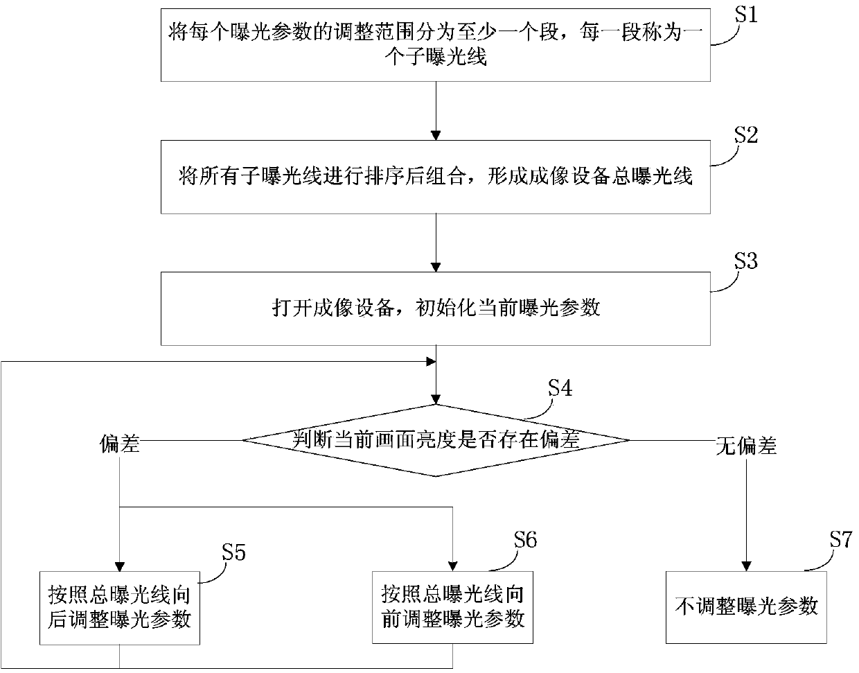
[0046] Such as figure 1 As shown, a method for automatic exposure control of an imaging device in this embodiment includes steps:

[0047] Step S1. Divide the adjustment range of each exposure parameter into at least one segment, each segment is called a sub-exposure line, and the two endpoints of each sub-exposure line represent the adjustment range of the sub-exposure line.

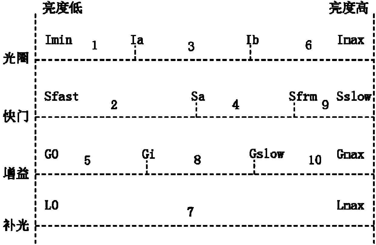
[0048] Such as figure 2 As shown, the exposure parameters of this embodiment include aperture, shutter, gain and fill light, and the adjustment range of each exposure parameter is as follows:

[0049] For the aperture, the aperture adjustment range is divided into three sections from Imin to Imax, namely three sub-exposure lines, Imin-Ia is a sub-exposure ...


PUM


Abstract

The invention discloses an automatic exposure control method and device for imaging equipment. Each exposure parameter is divided into a plurality of sections, each section is called as a sub exposure line, and the sub exposure lines are sequenced and then combined to form a main exposure line of the imaging equipment. After the imaging equipment is turned on, the deviation between a current screen brightness and a target screen brightness is judged, the exposure parameters are adjusted according to the main exposure line of the imaging equipment if the deviation exists, and the exposure parameters are not adjusted if the current screen brightness is within the range of the target screen brightness. The automatic exposure control device for the imaging equipment comprises a control module, a brightness evaluation module and an exposure parameter adjusting module. The method and the device are universal, the exposure parameters can be adjusted into reasonable values under a normal lighting condition, imaging effects are optimized, the exposure parameters can be adjusted into maximum values under an extreme lighting condition, the imaging effects cannot be worse than those of a traditional scheme, and overexposure can be effectively suppressed.

Description


Claims


Application Information

Patent Timeline
Owner ZHEJIANG UNIVIEW TECH CO LTD
Learn More