
Method and arrangement for detecting harmful substances

a detection method and harmful substance technology, applied in the field of detection methods and arrangements for harmful substances, can solve the problems of insufficient selectivity in order to detect harmful substances with the necessary reliability, many harmful substances cannot be detected, and the detection of war materials is too sensitive for detection, so as to improve the measuring operational readiness of the measuring system, prevent excessive exposure of ims, and improve the effect of measuring rang

Active Publication Date: 2006-10-05
AIRSENSE ANALYTICS
View PDF9 Cites 18 Cited by
  • Summary
  • Abstract
  • Description
  • Claims
  • Application Information

AI Technical Summary

Benefits of technology

[0020] It is an object of the invention to provide a method and an arrangement for detecting the above-mentioned harmful substances. It is a further object of the invention to compensate for or minimize the disadvantages of the IMS.
[0023] Some of the disadvantages of the IMS can be eliminated via suitable combinations of the IMS and other detectors. The additional detectors are to detect the harmful substances which are not measured by the IMS. A PID can detect, for example, the aromatics such as benzene. Further compounds such as phosgenes can be detected with electrochemical cells having lower detection limits. The cross sensitivity of the MOS sensors can be utilized in order to detect other harmful substances such as carbon monoxide. A further aid for improving the selectivity of the IMS can be realized via additional metered reaction gases. According to U.S. Pat. No. 4,551,624, the selectivity of the system is improved in the positive operating mode with respect to phosphor organic compounds, such as warfare substances, by the additional metering of acetone. The selectivity of the system improves in the negative operating mode with respect to nitrogen organic compounds, such as explosives, when carbon tetrachloride is used.
[0025] A controlled additional metering of a reference gas (such as purified fresh air at the inlet) can prevent that an excessive exposure of the IMS takes place. As a control variable for the dilution, the IMS or preferably a more rapid detector (such as a MOS sensor) can be used. Additionally, the measuring range of the IMS can, in this way, be improved by an order of magnitude of one to two.
[0026] The system can also be continuously flushed or rinsed with fresh air in the switched-off state in order to improve the measuring operational readiness of the measuring system after switch-on. A cleansing gas such as ozone from an ozone source can be additionally utilized in order to degrade contamination in the measuring system so that the system is more rapidly operationally ready.

Problems solved by technology

However, these detectors are too insensitive for detecting warfare materials.
Furthermore, their selectivity is often insufficient in order to detect harmful substances with the necessary reliability.
What is disadvantageous here is that many harmful substances cannot be detected.
Furthermore, it is disadvantageous that PID-lamps are rapidly contaminated which leads to poorer signal exploitation.
These sensors have a relatively intense cross sensitivity and cannot be used for detecting individual substances or as warning devices because of the high rate of false alarms.
MOS sensors are characterized by very rapid response times after an exposure to gas; however, the sensors have the disadvantage that the decay times are significantly longer.
A determination of individual substances is nonetheless not possible with the detectors because, here too, cross sensitivities occur, that is, there are no electrochemical cells available for all substances.
It is disadvantageous that the membrane causes the measuring system to react with more inertia with respect to its response time.
What is especially disadvantageous in the IMS, is the long time duration which must be allowed to elapse until the system is again operationally ready for measurement after switching on the apparatus.
It is furthermore disadvantageous that, for short-term overdosing, the system is no longer measurement ready and must be flushed for several minutes up to hours.
It is also disturbing that the spectra are dependent on concentration.
A further problem is the in part low selectivity of the IMS.
One reason is that, often, the harmful substances of interest are not ionized because of competing reactions in the ionization chamber and therefore cannot be detected.
These competing reactions can lead to the situation that many harmful substances having lower proton affinities, such as many solvents, do not even appear in the spectrum, for example, in the presence of gases such as ammonia.
On the other hand, the detection of warfare substances can be made more difficult or even impossible by the presence of solvents in high concentrations (ppm).
Furthermore, warfare substances having low proton affinity or electron affinity are not determined with the required detection limits.
A further disadvantage of the IMS is the limited measuring range which, for example, for a beta radiator as ionization source, amounts to typically maximally two orders of magnitude.
A quantitative statement is therefore difficult.
It is furthermore problematic that many harmful substances exhibit a low vapor pressure so that the detection limits of the detectors are not adequate in order to register these limits.
In the last two mentioned publications, it is disadvantageous that the measuring method is very complex and expensive because of the use of a gas chromatographic device.
However, in this publication, there is no suggestion as to in what manner the IMS is coupled to the additional detectors.
Furthermore, there are no measures described which prevent the measuring range of the IMS to be exceeded or that there be a drop therebelow during the measurement.

Method used


Image

  • Method and arrangement for detecting harmful substances
  • Method and arrangement for detecting harmful substances

Examples


Embodiment Construction

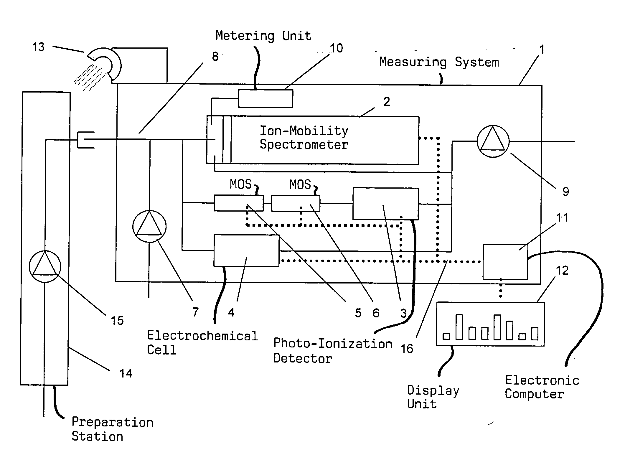
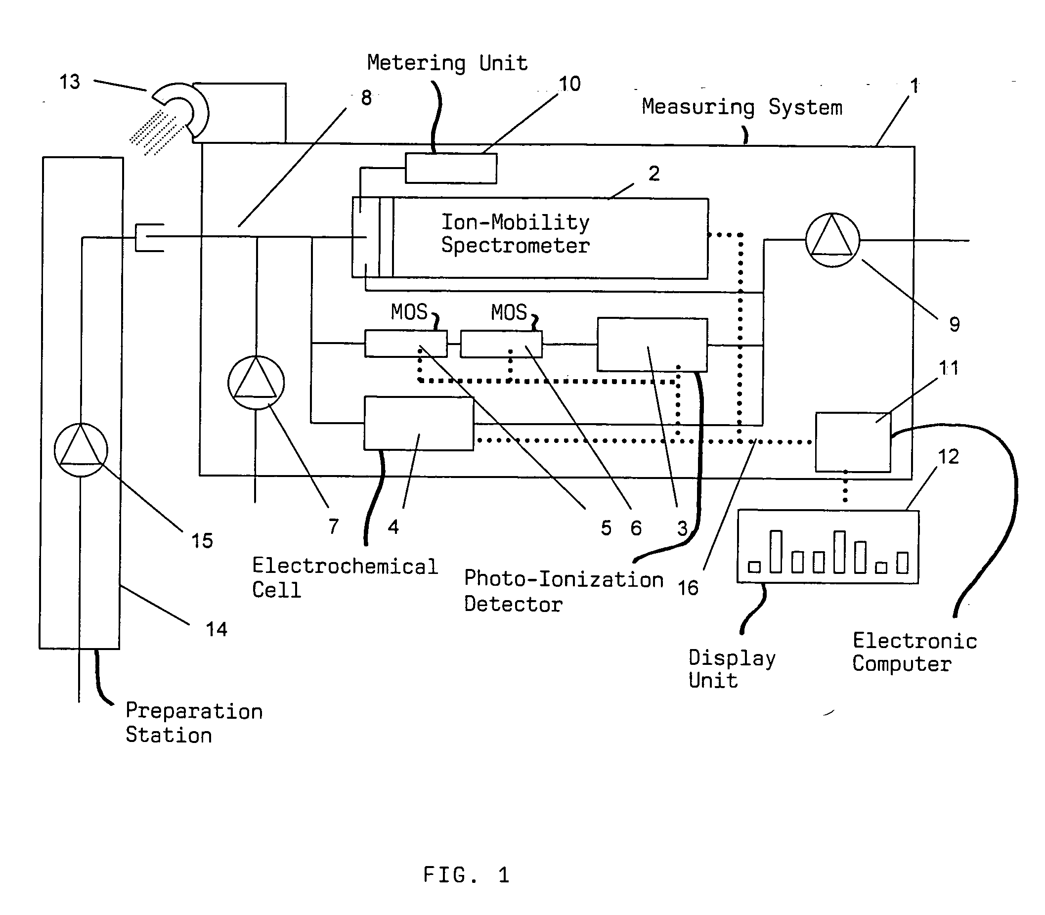
[0028] The arrangement of the invention primarily comprises a measuring system 1 which includes, for example, a combination of an IMS 2, a PID 3, an EC 4 and two MOS (5, 6). The gas to be measured is drawn by suction via a pump 9 and reaches the IMS and the other detectors via a split of the measurement gas path. The path to the other detectors is, in turn, subdivided into two paths. One path leads to the EC 4 and the other path leads via the MOS (5, 6) to the PID 3. The gas paths are thereafter brought together before they are connected to the pump 9.

[0029] The measuring system includes a further pump 7 for admixing a reference gas into the measurement gas path 8. The reference gas is drawn by suction by the above-mentioned pump 9. In order to go easy on the detectors, the measuring system is so operated that primarily the reference gas is measured. For low measuring signals, the flow rate of the pump 7 is reduced so that the portion of the ambient air to be measured increases. Th...


PUM

PropertyMeasurementUnit
concentrationaaaaaaaaaa
heightsaaaaaaaaaa
electron affinityaaaaaaaaaa

Abstract

A method and an arrangement detect harmful substances while eliminating or minimizing the drawbacks of an ion mobility spectrometer (IMS). The sample gas flow is mixed with a reference gas utilizing a pump (7). A reaction gas is supplied via a metering unit (10) to the ion-mobility spectrometer (2) when complex ion-mobility spectrometer spectra are present. The measurement signals obtained as to the gas-quantity ratio between the sample gas and the reference gas are adapted to the original concentration and are then compared to previously defined and stored measured values via a signal height comparison or a pattern recognition. The measuring system is rinsed following the measurement phase by feeding the reference gas and is cleaned by metering an additional cleansing gas when harmful substances are detected which could be rinsed away. Such methods and measuring systems are used for identifying harmful substances in ambient air.

Description

CROSS REFERENCE TO RELATED APPLICATIONS [0001] This is a continuation of international patent application PCT / DE 2004 / 000427, filed Mar. 4, 2004, and claiming priority from German patent application no. 103 10 394.5, filed Mar. 7, 2003, and the entire content of both applications is incorporated herein by reference.FIELD OF THE INVENTION [0002] The invention relates to a method for determining gaseous harmful substances utilizing a combination of an ion mobility spectrometer and additional detectors which detect harmful substances which cannot be detected by the ion mobility spectrometer. The invention is also directed to an arrangement for carrying out the method of the invention. BACKGROUND OF THE INVENTION [0003] Methods and measuring systems of the above kind are utilized for identifying harmful substances in ambient air. The detection of harmful substances after accidents or catastrophes is important, for example, for emergency personnel of fire and police departments. A list o...

Claims


Application Information

Patent Timeline
Patent Type & Authority Applications(United States)
IPC IPC(8): H01J49/00B01D59/44G01N27/64
CPCG01N27/622G01N27/66
Inventor WALTE, ANDREASMUNCHMEYER, WOLF
Owner AIRSENSE ANALYTICS
Learn More