Emergency lamp switch control circuit

A technology for switching control circuits and emergency lights, which is applied in the layout of electric light circuits, electric light sources, light sources, etc., can solve problems such as increasing the cost of lamps, extinguishing emergency lights, and reducing product market competitiveness.

Active Publication Date: 2013-12-04
OCEANS KING LIGHTING SCI&TECH CO LTD +1
View PDF3 Cites 0 Cited by
  • Summary
  • Abstract
  • Description
  • Claims
  • Application Information

AI Technical Summary

Problems solved by technology

Therefore, after the mains fails, the emergency light starts and will go out after being lit for a limited time, but when the circuit maintenance personnel cannot rush from the station to the scene for repair or construction in time, the emergency light will go out due to the exhaustion of the battery
At this time, the circuit maintenance personnel need lighting to repair the circuit, and the power of the emergency light has been released, which makes the maintenance process very inconvenient
At present, the solution to prolong the emergency time is mainly to increase the capacity of the battery to prolong the emergency time, but increasing the battery capacity will greatly increase the cost of the lamp and reduce the market competitiveness of the product

Method used


Image

  • Emergency lamp switch control circuit
  • Emergency lamp switch control circuit
  • Emergency lamp switch control circuit

Examples


Embodiment Construction

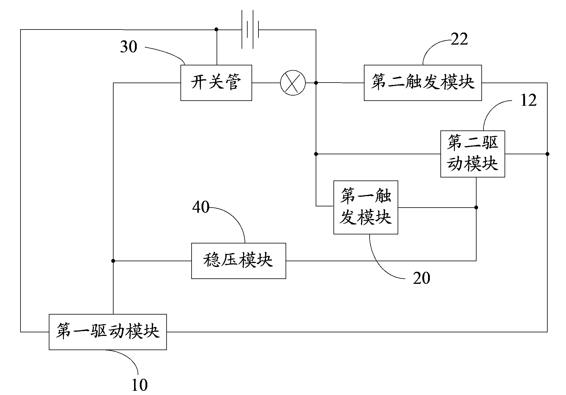
[0028] like figure 1 Shown is a schematic structural diagram of the emergency light switch control circuit. The emergency light switch control circuit is used to control the start or extinguishment of the emergency light in an emergency situation, including a switch tube 30 for controlling the start or extinguishment of the emergency light, a first trigger module 20 for sending a first trigger signal, and a second trigger module for sending a second trigger signal. The second trigger module 22 for triggering the signal, the second driving module 12 for driving the switch tube 30 to turn off when receiving the first trigger signal, and the second drive module 12 for driving the switch tube 30 to turn on when receiving the second trigger signal A driving module 10 and a voltage stabilizing module 40 for providing a stable voltage drop between the first driving module 10 and the second driving module 12 .

[0029] The first driving module 10 includes an input terminal, an output...


PUM


Abstract

An emergency lamp switch control circuit is used for controlling an emergency lamp to be turned on or off under the emergency conditions. The emergency lamp switch control circuit comprises a switch tube for controlling the emergency lamp to be turned on or off, a first trigger module for sending out first trigger signals, a second trigger module for sending out second trigger signals, a second driving module for driving the switch tube to be disconnected when receiving the first trigger signals, a first driving module for driving the switch tube to be connected when receiving the second trigger signals and a voltage stabilizing module for providing stable voltage drop between the first driving module and the second driving module. According to the emergency lamp switch control circuit, by utilizing the first driving module to control the switch tube to be connected and utilizing the second driving module to control the switch tube to be disconnected, the emergency lamp connected with the switch tube is controlled to be turned on or off. Accordingly, the working state of the emergency lamp can be controlled when the emergency lamp is in the working state.

Description

technical field [0001] The invention relates to an emergency light circuit, in particular to an emergency light switch control circuit. Background technique [0002] When the mains power fails, the emergency light will automatically start immediately, and the power supply time of the battery in the emergency light is limited. Therefore, after the mains fails, the emergency light will start and will go out after being lit for a limited time, but when the circuit maintenance personnel cannot rush from the station to the scene for repair or construction in time, the emergency light will go out due to the exhaustion of the battery. At this time, the circuit maintenance personnel need lighting to repair the circuit, and the power of the emergency light has been released, which makes the maintenance process very inconvenient. At present, the solution to prolong the emergency time is mainly to increase the capacity of the battery to prolong the emergency time, but increasing the b...

Claims


Application Information

Patent Timeline
Patent Type & Authority Applications(China)
IPC IPC(8): H05B37/02
Inventor 周明杰王现中
Owner OCEANS KING LIGHTING SCI&TECH CO LTD
Why Eureka
Try Eureka