
a camera array

A camera and camera module technology, applied in image communication, TV, color TV components, etc., can solve the problems of large shooting area, high price of X-Y mobile platform, difficult and fast detection, etc., to achieve large shooting area and simple structure , low cost effect

Active Publication Date: 2016-05-25
徐州火晨高科技有限公司
View PDF7 Cites 0 Cited by
  • Summary
  • Abstract
  • Description
  • Claims
  • Application Information

AI Technical Summary

Problems solved by technology

[0007] The present invention mainly solves the problems existing in the prior art that it is difficult to quickly detect a large-area circuit board and the price of an X-Y mobile platform is high, and provides a camera array with a large shooting area, no focusing problem, good stability, low cost, and high speed

Method used


Image

  • a camera array
  • a camera array
  • a camera array

Examples


Embodiment

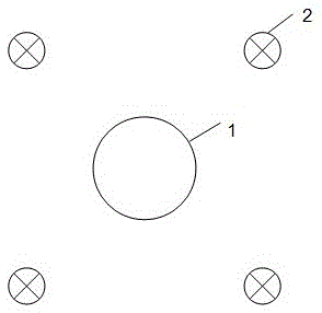
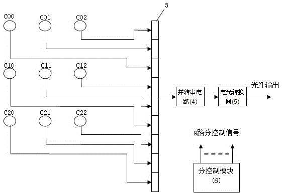
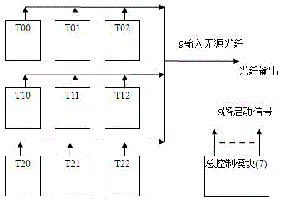
[0036] Embodiment: a kind of camera array of this embodiment, as image 3 As shown, it includes 9 camera modules (T00 to T22) arranged in a 3×3 square array and a total control module 7. The structure of each camera module is as follows figure 2 As shown, it includes sub-control module 6, 9-way selection switch 3, parallel-to-serial circuit 4, electro-optical converter 5, optical fiber interface and 9 basic modules (C00 to C22) arranged in a 3×3 square matrix. The structure of each basic module is as follows figure 1 As shown, it includes a video camera 1 and four LED lighting lamps 2 . Four LED lighting lamps are arranged in a square in the form of 2×2, and the camera lens is in the center of the square formed by four LED lighting lamps. The output terminals of the camera are connected to the input terminals of the 9-way selection switch, and the The output end is connected to the input end of the electro-optical converter through a parallel-to-serial circuit, the output ...


PUM


Abstract

The invention discloses a camera array including a total control module and a plurality of camera modules arranged in a square array. Each camera module includes a sub-control module, 9 paths of selective switches, a parallel-to-serial circuit, an electronic-to-optical convertor, an optical-fiber interface and 9 basic modules arranged into a 3*3 square array. Each basic module includes a camera and four illuminating lamps. In each basic module, the four illuminating lamps are arrayed into a 2*2square and a lens of the camera is arranged in the center of the square. In each camera module, the cameras are connected with the 9 paths of switches; output ends of the 9 paths of selective switches are connected to an input end of the electronic-to-optical converter through the parallel-to-serial circuit; the electronic-to-optical convertor is connected with a processing device through the optical-fiber interface; and the sub-control module is connected with the 9 paths of switches and the cameras. The total control module is connected with the sub-control modules. The cameras shoot sequentially and transmit images to the processing device through optical fibers. The camera array is applicable to the field of high-precision vision detection of circuit boards and the like.

Description

technical field [0001] The invention relates to the field of photography and imaging, in particular to a low-cost camera solution applied to the fields of automatic detection of large-format circuit boards, films, printed and dyed products, and the like. Background technique [0002] With the increasing maturity of machine vision algorithm software and the drop of computer hardware prices, its application in industrial inspection applications is becoming more and more popular. The use of machine vision technology to detect product appearance quality in various applications is a major application, including automatic detection of circuit boards in the electronic field and other fields, such as X-ray films in the medical field, printed products in the printing and dyeing field, etc. [0003] Take the circuit board as an example. The circuit board is the core of electronic products. The technological level of circuits and electronic components is getting higher and higher. The ...

Claims


Application Information

Patent Timeline
Patent Type & Authority Patents(China)
IPC IPC(8): H04N5/232H04N5/235H04N7/18
Inventor 鞠怡明鞠见
Owner 徐州火晨高科技有限公司
Learn More