

Tunnel fire-fighting device
A technology for fire protection devices and tunnels, applied in fire rescue and other directions, can solve problems such as the device cannot continue to move forward, the device cannot continue to work, etc., and achieves the effect of improving convenience, applicability, and ease of use.
- Summary
- Abstract
- Description
- Claims
- Application Information
AI Technical Summary
Problems solved by technology
Method used
Image

Examples
Embodiment 1
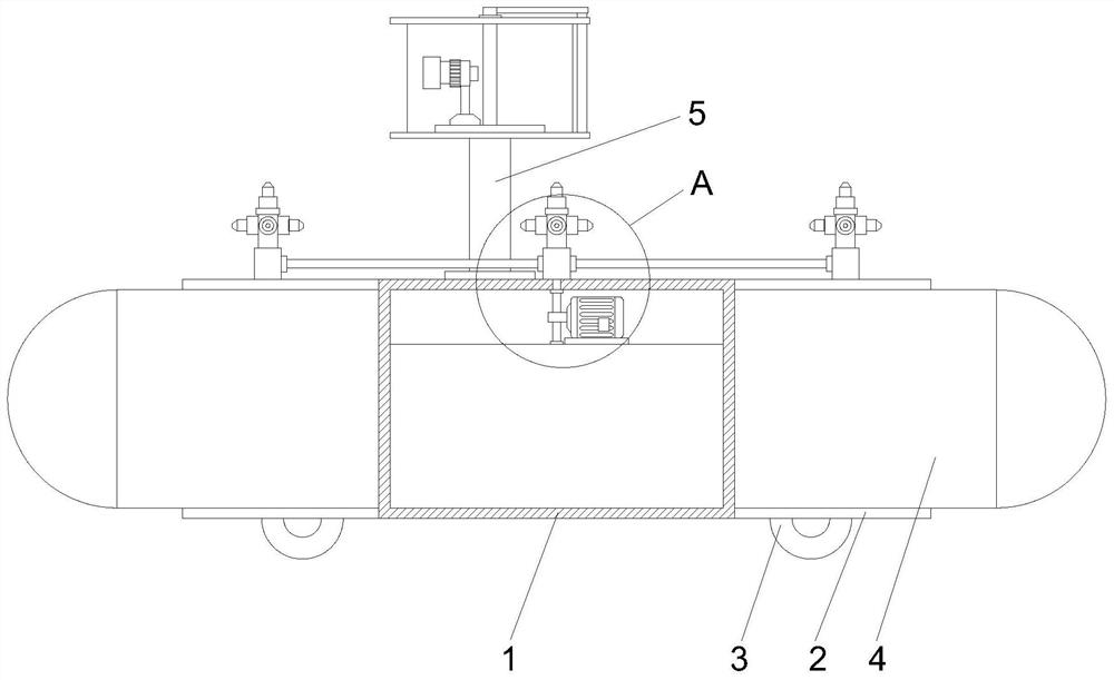
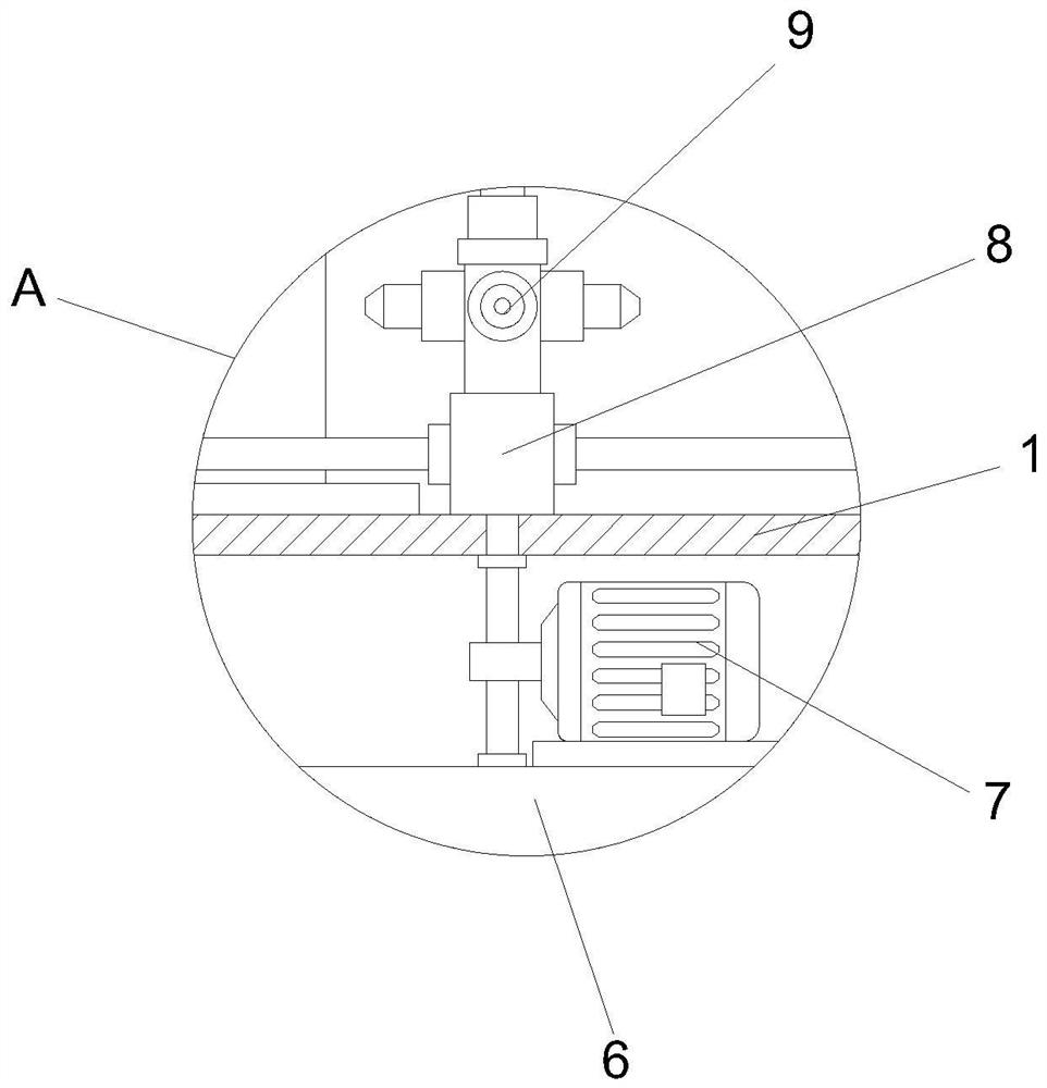
[0032] Such as Figure 1-9 As shown, the present invention provides a tunnel fire-fighting device, comprising a main body frame 1, an extension frame 2 is fixedly connected to both sides of the body frame 1, and a moving wheel 3 is fixedly installed on the bottom of the extension frame 2, and the two sides of the extension frame 2 Both are fixedly installed with a clearing mechanism 4, the top of the main body frame 1 is fixedly installed with a detection rod 5, the bottom of the inner cavity of the main body frame 1 is fixedly installed with a water storage tank 6, and the top of the water storage tank 6 is fixedly installed with a booster pump 7 , the input end of the booster pump 7 is fixedly connected to the water storage tank 6 through a water pipe, the top of the main body frame 1 and the extension frame 2 are fixedly installed with a water pipe joint 8, and the output end of the booster pump 7 is connected to the water pipe joint 8 through a water pipe Fixedly connected...
Embodiment 2
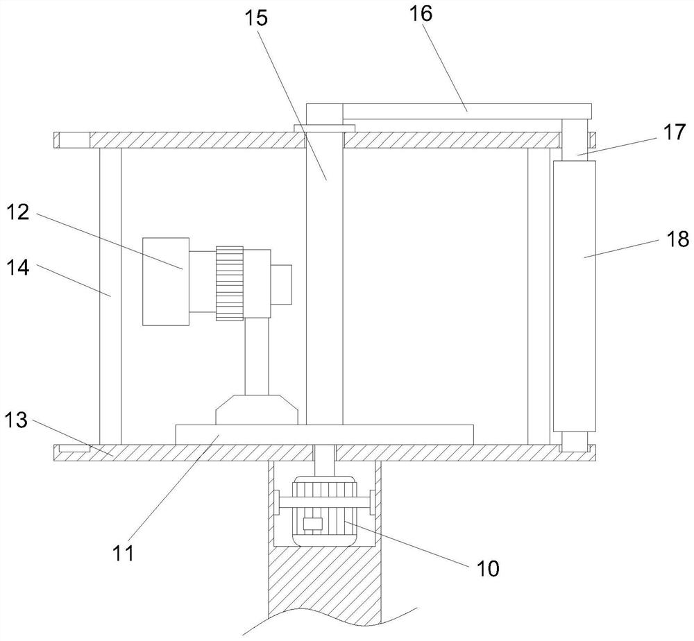
[0037] Such as Figure 1-9 As shown, on the basis of Embodiment 1, the present invention provides a technical solution: preferably, the cleaning mechanism 18 includes an installation collar 19, and the installation collar 19 is sleeved on the outer wall of the cleaning roller 17, and the installation collar 19 A soft brush 20 is fixedly installed on the outer wall, a soaking box 21 is fixedly installed on the outer wall of the installation collar 19, and a sponge wipe 22 is fixedly installed on the side of the soaking box 21 away from the installation collar 19, and the inner cavity of the soaking box 21 is filled with Glass water, the water soaking box 21 is provided with a through hole near the side of the sponge wipe 22, through which the water soaking box 21 is provided, the glass water filled in the water soaking box 21 is immersed in the sponge wipe 22 through the through hole, and the sponge wipe 22 is continuously moistened. Assist the soft brush 20 to clean the surfac...
Embodiment 3
[0039] Such as Figure 1-9 Shown, on the basis of embodiment 1, the present invention provides a kind of technical scheme: preferably, on pulley one 28 transmission is connected with drive belt 29, and drive belt 29 is set to two, and wherein one drive belt 29 is away from the end transmission of pulley one 28 Be connected with belt pulley two 30, another transmission belt 29 is connected with belt pulley two 30 transmissions, and another transmission belt 29 is connected with belt pulley three 31 far away from the transmission of an end of belt pulley two 30, and belt pulley three 31 is fixedly connected with obstacle removal gear 32, obstacle removal gear 32 The upper meshing is provided with the obstacle removal crawler 33, and the obstacle removal crawler 33 is fixedly installed with the obstacle removal hand 34, and the center of the right side of the crushing seat 25 is fixedly equipped with a crushing rod 35, and the right side of the crushing seat 25 is fixedly installe...
PUM
 Abstract
Description
Claims
Application Information