
Emergency braking intervention system and method before collision

An emergency braking and controller technology, applied in the field of automotive safety systems, can solve the problems of aggravating tire wear, increasing braking distance, and increasing the possibility of collision, so as to ensure safety, reduce distance, and improve safety. sexual effect

Active Publication Date: 2014-01-01
DONGFENG MOTOR CORP HUBEI
View PDF7 Cites 22 Cited by
  • Summary
  • Abstract
  • Description
  • Claims
  • Application Information

AI Technical Summary

Benefits of technology

This technology uses various safest distances modeled into road surfaces based upon their ability to prevent accidents or improve traffic flow. It ensures optimal performance while minimizing impact on human health and wellbeing. When there are no more obstacles along the way, they will be avoided until needed. Additionally, if another car starts up near them, its speed may decrease slightly after being stopped without hitting any objects. By sending certain types of signals like brakes, engines, and indicators to help reduce these negative factors, drivers experience less discomfort compared to traditional methods. Overall, this technology helps maintain better efficiency and security over all aspects of travel.

Problems solved by technology

This patents describes how drivers are often mistakenly operating their own vehicles without being aware they may collide into other cars near them. These crashes happen because there were incorrect decelerations made while driving along poor surfaces like rocks or rainwater puddles. There was no way to prevent these mistakes until after all, leading to longer times needed for reactions than expected. Additionally, existing emergency crash avoidance devices did little more harming the environment compared to previous designs.

Method used


Image

  • Emergency braking intervention system and method before collision

Examples


Embodiment Construction

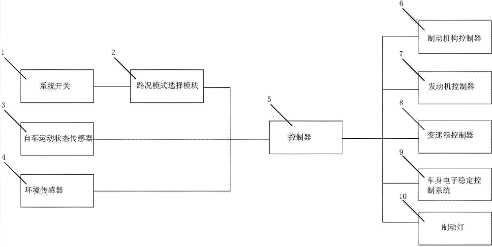
[0028] Below in conjunction with accompanying drawing and specific embodiment the present invention is described in further detail:

[0029] figure 1 The pre-collision emergency braking intervention system shown includes a vehicle motion state sensor 3, an environmental sensor 4, a braking mechanism controller 6, an engine controller 7 and a gearbox controller 8, and is characterized in that it also includes a system switch 1. The road condition mode selection module 2, the vehicle body electronic stability control system 9, which can judge the degree of danger according to the road condition mode, the state of the vehicle movement and the environment state, and send a control signal to the controller 5, wherein the system switch 1 is connected to the road condition The mode selection module 2, the signal output end of the road condition mode selection module 2, the vehicle motion state sensor 3 and the environment sensor 4 are all connected to the signal input end of the cont...


PUM


Abstract

The invention discloses an emergency braking intervention system before collision. The system comprises an own car motion state sensor, an environment sensor, a braking mechanism controller, a motor controller, a gearbox controller, a system switch, a road condition mode selection module, a car body electronic stability control system and a controller which is capable of determining danger degrees according to the road condition mode, the own car motion state and the environment state and emits control signals. The system switch is connected with the road condition mode selection module, the road condition mode selection module, the own car motion state sensor and the environment sensor are all connected with the controller, a control single output end of the controller is connected with a control signal input end of the braking mechanism controller and a control signal input end of the motor controller, a control signal input end of the gearbox controller and a control signal input end of the car body electronic stability control system. By means of the system and the method, damage to a motor and a transmission system by emergency braking is reduced, the emergency braking distance is shortened, and the safety of the car during traveling is improved.

Description


Claims


Application Information

Patent Timeline
Owner DONGFENG MOTOR CORP HUBEI
Learn More