
Vacuumizing system of turbine

A technology of vacuum pumping system and steam turbine, which is applied in the field of vacuum pumping system, can solve the problems of high energy consumption of vacuum pump, reduced pumping performance of vacuum pump, inability to maintain vacuum of condenser, etc.

Active Publication Date: 2014-01-01
盐城市勤创机械有限公司
View PDF5 Cites 11 Cited by
  • Summary
  • Abstract
  • Description
  • Claims
  • Application Information

AI Technical Summary

Problems solved by technology

Especially in summer, due to the high working water temperature, the pumping performance of the vacuum pump drops sharply, so that one vacuum pump cannot maintain the vacuum of the condenser, and two vacuum pumps need to be turned on at the same time to maintain the vacuum of the condenser, resulting in high energy consumption of the vacuum pump. high

Method used


Image

  • Vacuumizing system of turbine
  • Vacuumizing system of turbine

Examples


Embodiment Construction

[0009] The present invention will be described in further detail below through specific implementation examples and in conjunction with the accompanying drawings.

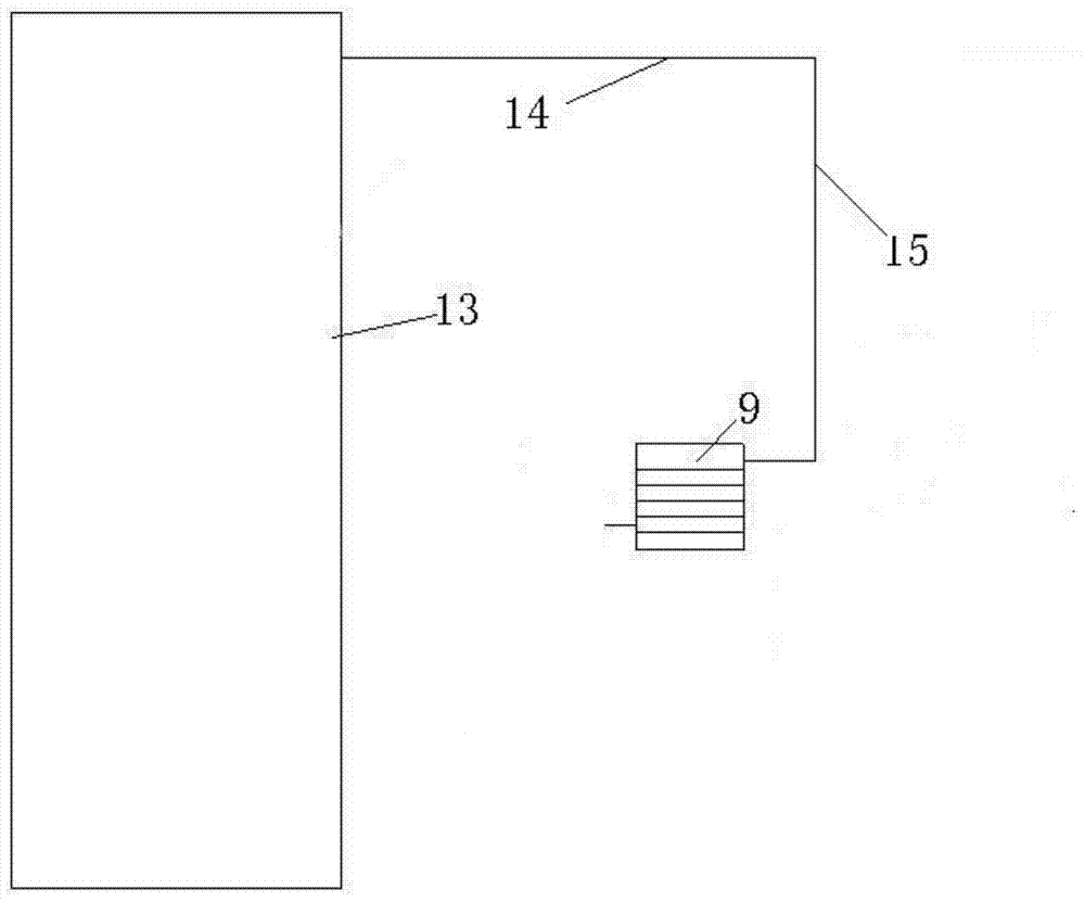
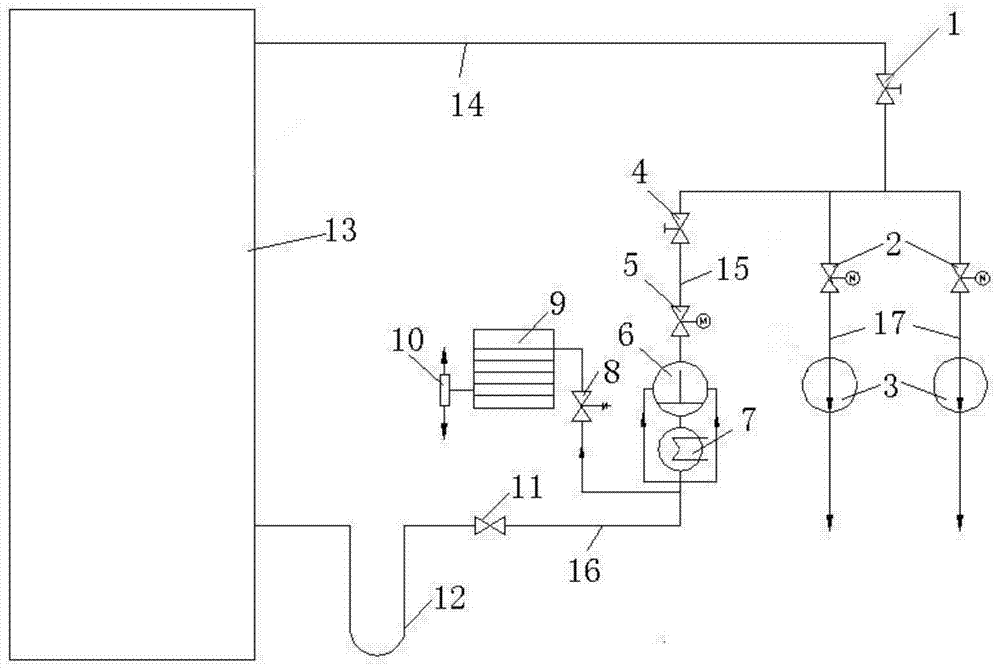
[0010] A steam turbine vacuum pumping system, comprising: a steam turbine condenser 13, a dry vacuum pump 9, a main pipeline 14 and a first connecting pipeline 15; one end of the main pipeline 14 is connected with the gas extraction port of the steam turbine condenser 13; the main pipeline 14 The other end is connected to one end of the first connecting pipe 15 ; the inlet of the dry vacuum pump 9 is connected to the other end of the first connecting pipe 15 .

[0011] The steam turbine vacuum pumping system provided in Embodiment 1 of the present invention, such as figure 1 As shown, the steam-gas mixture extracted from the steam turbine condenser 13 first passes through the exhaust port of the steam turbine condenser 13 and enters the inlet of the dry vacuum pump 9 through the main pipeline 14 and the first conne...


PUM


Abstract

The invention relates to the field of vacuumizing systems, and particularly relates to a vacuumizing system of a turbine. The vacuumizing system comprises a turbine condenser, a dry vacuum pump, a main pipeline and a first connecting pipeline, wherein one end of the main pipeline is connected with the extraction opening of the turbine condenser, the other end of the main pipeline is connected with one end of the first connecting pipeline, and the inlet of the dry vacuum pump is connected with the other end of the first connecting pipeline. According to the vacuumizing system of the turbine, water is not needed to be used as a vacuumizing medium, so that the limitation to a water medium of a conventional water ring vacuum pump and a conventional water jet air ejector is broken through, and the influence that the exhaust capacity of the water ring vacuum pump and the water jet air ejector decreases with the increase of the water temperature is overcome; an existing water ring vacuum pump and an existing water jet air ejector are reconstructed, and a steam-gas mixed gas of the condenser is directly extracted, so that high efficiency and energy saving of the vacuumizing system are realized.

Description

technical field [0001] The invention relates to the field of vacuum pumping systems, in particular to a steam turbine vacuum pumping system. Background technique [0002] A steam turbine vacuum system generally includes a steam turbine condenser and a vacuum device. The vacuuming device of the traditional steam turbine vacuuming system generally adopts a water ring vacuum pump or a water jet pump. These vacuuming devices are all water medium vacuum pumps, which are a kind of rough vacuum pumping device. The change of working water temperature directly affects its pumping. performance. Especially in summer, due to the high working water temperature, the pumping performance of the vacuum pump drops sharply, so that one vacuum pump cannot maintain the vacuum of the condenser, and two vacuum pumps need to be turned on at the same time to maintain the vacuum of the condenser, resulting in high energy consumption of the vacuum pump. high. Contents of the invention [0003] An...

Claims


Application Information

Patent Timeline
Patent Type & Authority Applications(China)
IPC IPC(8): F04B37/14F04B41/06
Inventor 于翔
Owner 盐城市勤创机械有限公司
Learn More