Method and device for sending contact information

A technology for contacting information and equipment, applied in the field of communication, which can solve problems such as time-consuming and complex

Inactive Publication Date: 2014-01-01
BEIJING OAK PACIFIC NETSCAPE TECH DEV
3 Cites 11 Cited by

AI-Extracted Technical Summary

Problems solved by technology

Usually, the contact information can only be communicated orally, in writing, et...

Method used

[0013] A two-dimensional code generally refers to a two-dimensional pattern that uses a black and white (or two other colors) pattern to represent binary data and is scanned by a device to obtain the information contained therein. Using QR codes can conveniently and reliably tra...

Abstract

The invention provides a method and device for sending contact information. The method includes the following steps that a two-dimension code including one or more pieces of contact information is generated; the two-dimension code is displayed on a lock screen interface of a mobile device so as to be read by other devices.

Application Domain

Digital data protectionRecord carriers used with machines +2

Technology Topic

Lock screenHuman–computer interaction +1

Image

  • Method and device for sending contact information
  • Method and device for sending contact information
  • Method and device for sending contact information

Examples

  • Experimental program(1)

Example Embodiment

[0010] The principle and spirit of the present invention will be described below with reference to several exemplary embodiments. It should be understood that these embodiments are given only to enable those skilled in the art to better understand and then implement the present invention, but not to limit the scope of the present invention in any way.
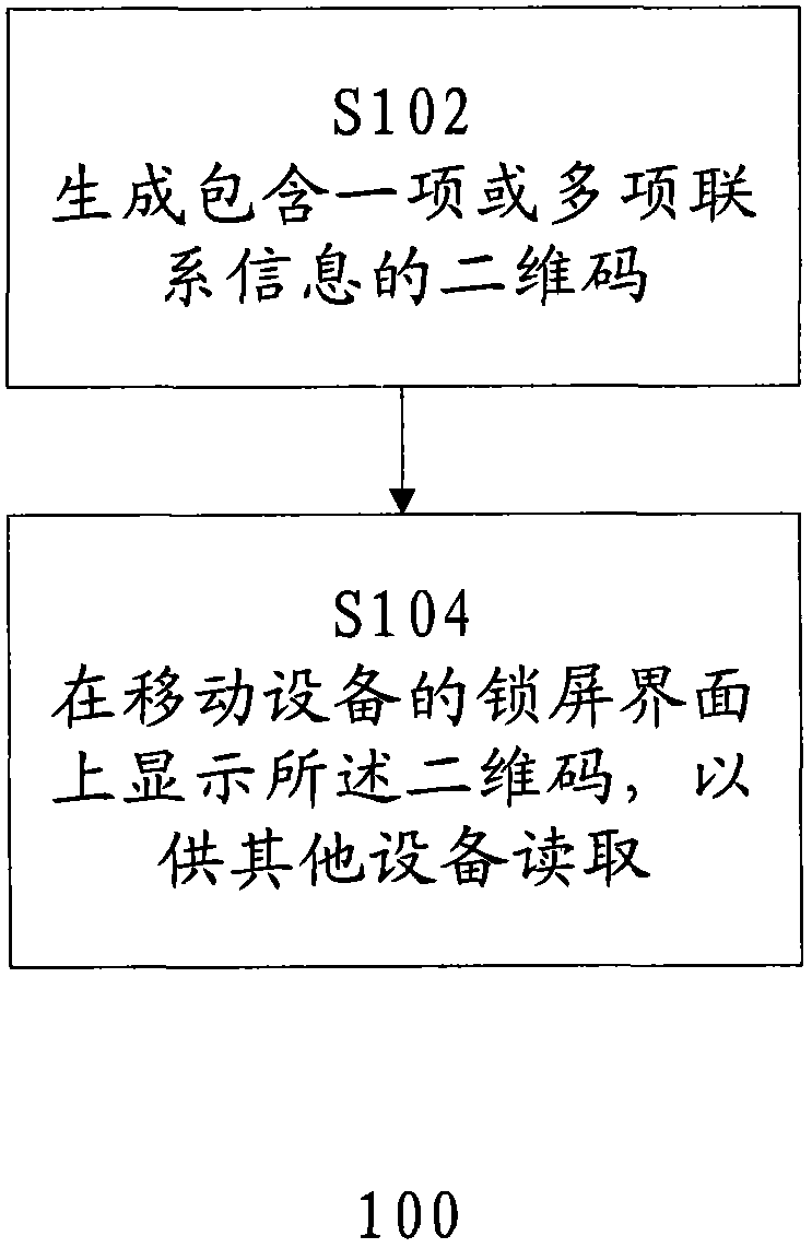
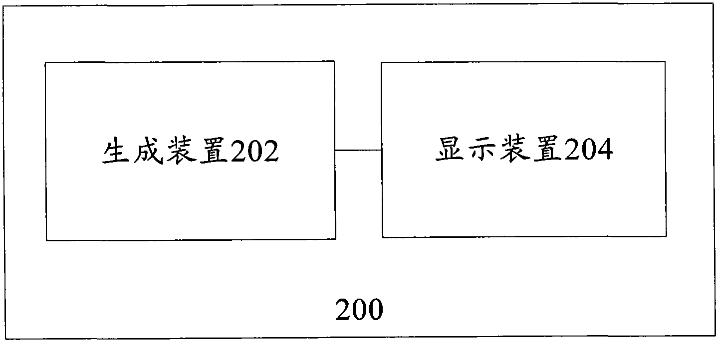
[0011] Reference below figure 1 , Which shows a flowchart of a method 100 for sending contact information according to an embodiment of the present invention.
[0012] In step S102, a QR code containing one or more contact information is generated.
[0013] A two-dimensional code usually refers to a two-dimensional pattern that uses black and white (or two other colors) patterns to represent binary data and can be scanned by a device to obtain the information contained therein. The two-dimensional code can be used to conveniently and reliably transmit various types of information.
[0014] In one embodiment, the contact information may include one or more of the following: phone number, fax number, communication address, email, personal website, social network account, instant messaging tool account, and application account. Other existing or future contact information types are also possible.
[0015] The contact information can be encoded as binary data using any known encoding scheme, and formed as a two-dimensional code according to two-dimensional code standards such as QR code and PDF417.
[0016] In an embodiment, generating the two-dimensional code may include encrypting the two-dimensional code. The binary data encoded from the contact information can be encrypted. Encryption can be performed by various known encryption methods. For example, only receiving devices that know the encryption method can decrypt the contact information, thereby improving the security of the contact information.
[0017] In step S104, the two-dimensional code is displayed on the lock screen interface of the mobile device for other devices to read.
[0018] Mobile devices can include mobile phones, personal digital assistants (PDAs), pagers, mobile computers, desktop computers, televisions, portable gaming devices, notebook computers, cameras, camcorders, global positioning system (GPS) devices, and other types of electronic systems .
[0019] The lock screen interface of a mobile device usually refers to an interface provided for the purpose of avoiding misoperation of the mobile device, etc. The interface is usually accessed by pressing a specific button or turning on an external power supply when the mobile device is in a screen off state, or When the mobile device is in a state where the screen is off, the user enters due to the appearance of a new message or other reminders, and the user usually needs to perform a specific operation on the interface to enter the "unlocked" state, that is, the normal operation state. However, it should be understood that the lock screen interface can also be entered through a variety of other operations in various other states of the mobile device, for example, by clicking a specific icon in a normal operating state. Due to the above characteristics of the lock screen interface, regardless of the current state of the mobile device, the user can usually quickly enter the lock screen interface with a simple operation.
[0020] Therefore, by displaying a two-dimensional code containing contact information on the lock screen of a mobile device for other devices to read, the process of sending contact information is simplified and accelerated.
[0021] The QR code can be displayed at any position on the lock screen interface and can be displayed in any size, as long as it can be reliably read by other devices. In one embodiment, two or more two-dimensional codes can be generated and displayed. The two or more two-dimensional codes may respectively contain multiple different contact information of the same user, or may respectively contain the contact information of multiple users.
[0022] In one embodiment, the two-dimensional code is displayed on the lock screen interface of the mobile device in response to operating the mobile device. In one embodiment, the operation includes one or more of the following: clicking or sliding on the touch screen, pressing a button, and moving the mobile device. It should be understood that many other operations are also possible. In this way, the QR code will not be displayed every time you enter the lock screen interface, but will only be displayed when a specific operation is performed, thereby improving the security of contact information and maintaining the lock The screen interface is concise.
[0023] Reference below figure 2 , Which shows a schematic block diagram of a device 200 for sending contact information according to an embodiment of the present invention. The device 200 includes: a generating device 202, which is configured to generate a two-dimensional code containing one or more contact information; and a display device 204, which is configured to display the two-dimensional code on a lock screen interface for other Device read.
[0024] In an embodiment, the contact information may include one or more of the following: phone number, fax number, communication address, email, personal website, social network account, instant messaging tool account, and application account.
[0025] In an embodiment, the generating device may be further configured to encrypt the two-dimensional code.
[0026] In one embodiment, the display device may be configured to display the two-dimensional code on a lock screen interface of the mobile device in response to operating the mobile device.
[0027] In an embodiment, the operation may include one or more of the following: clicking or sliding on the touch screen, pressing a button, and moving the mobile device.
[0028] In one embodiment, the generating device and the display device may be configured to generate and display two or more two-dimensional codes.
[0029] For clarity, in figure 2 The sub-devices included in each device are not shown in. However, it should be understood that the devices described in the device 200 are different from the respective reference figure 1 The steps in the described method 100 correspond. Therefore, the above figure 1 The operations and features described in the method 100 are also applicable to the device 200 and the devices and sub-devices contained therein, and will not be repeated here.
[0030] It should be understood that the device 200 can be implemented in various ways. For example, in some embodiments, the device 200 may be implemented using software and/or firmware modules. In addition, the device 200 can also be implemented using hardware modules. For example, the device 200 may be implemented as an integrated circuit (IC) chip or an application specific integrated circuit (ASIC). The device 200 may also be implemented as a system on chip (SOC). In addition, the device 200 may also be implemented by using a combination of hardware modules and software and/or firmware modules. Other methods currently known or developed in the future are also feasible, and the scope of the present invention is not limited in this respect.
[0031] Reference below image 3 , Which shows a schematic block diagram of a mobile terminal 300 suitable for practicing the embodiments of the present invention. in image 3 In the example shown, the mobile terminal 300 is a mobile device with wireless communication capabilities. However, it can be understood that this is only exemplary and not restrictive. Other types of mobile terminals can also easily adopt the embodiments of the present invention, such as portable digital assistants (PDAs), pagers, mobile computers, mobile TVs, gaming devices, laptop computers, cameras, video recorders, GPS devices, and other types of Voice and text communication system. Stationary mobile terminals can also easily use the embodiments of the present invention.
[0032] The mobile terminal 300 includes one or antenna 312 that is operable to communicate with a transmitter 314 and a receiver 316. The mobile terminal 300 also includes a processor 312 or other processing elements, which provide signals to the transmitter 314 and receive signals from the receiver 316, respectively. The signal includes signaling information in accordance with the air interface standard of the appropriate cellular system, and also includes user voice, received data, and/or user generated data. In this regard, the mobile terminal 300 is capable of operating with one or more air interface standards, communication protocols, modulation types, and access types. As an example, the mobile terminal 300 can operate according to any of a plurality of first-generation, second-generation, third-generation, and/or fourth-generation communication protocols. For example, the mobile terminal 300 may be able to operate in accordance with the second-generation (G) wireless communication protocol IS-136 (TDMA), GSM, and IS-95 (CDMA), or in accordance with the first such as UMTS, CDMA2000, WCDMA and TD-SCDMA. Operate according to the third-generation (G) wireless communication protocol, or operate in accordance with the fourth-generation (4G) wireless communication protocol and/or similar protocols.
[0033] It can be understood that the processor 312 includes circuits required to implement the functions of the mobile terminal 300. For example, the processor 312 may include a digital signal processor device, a microprocessor device, various analog-to-digital converters, digital-to-analog converters, and other support circuits. The control and signal processing functions of the mobile terminal 300 are allocated among these devices according to their respective capabilities. The processor 312 may therefore also include functions for convolutional encoding and interleaving of messages and data before modulation and transmission. The processor 312 may additionally include an internal voice encoder, and may include an internal data modem. In addition, the processor 312 may include functions for operating one or more software programs that may be stored in the memory. For example, the processor 312 may be capable of operating a connection program, such as a conventional web browser. The connection program may then allow the mobile terminal 300 to transmit and receive web content (such as location-based content and/or other web page content), for example, in accordance with Wireless Application Protocol (WAP), Hypertext Transfer Protocol (HTTP), etc.
[0034] The mobile terminal 300 may also include a user interface, which may include, for example, a headset or speaker 324, a ringer 322, a microphone 326, a display screen 328, and an input interface 331, all of which are coupled to the processor 312. The mobile terminal 300 may include a keypad 330. The keypad 330 may include traditional number keys (0-9) and related keys (#, *), as well as other keys for operating the mobile terminal 300. Alternatively, the keypad 330 may include a traditional QWERTY keypad arrangement. The keypad 330 may also include various soft keys associated with functions. The mobile terminal 300 may also include a camera module 336 for capturing still and/or moving images.
[0035] In particular, the display screen 328 may include a touch screen and/or a proximity screen, and the user may operate the mobile terminal 300 by directly operating the screen. At this time, the display screen 328 serves as both an input device and an output device at the same time. In such an embodiment, the input interface 331 may be configured to receive input provided by the user on the display screen 328 through, for example, an ordinary pen, a dedicated stylus, and/or a finger, including pointing input and gesture input. The processor 312 may be configured to detect such input and recognize the user's gestures.
[0036] In addition, the mobile terminal 300 may include an interface device such as a joystick or other interfaces for input. The mobile terminal 300 also includes a battery 334, such as a vibrating battery pack, for powering various circuits required to operate the mobile terminal 300, and optionally providing mechanical vibration as a detectable output.
[0037] The mobile terminal 300 may further include a user identification module (UIM) 338. UIM 338 is usually a memory device with a built-in processor. The UIM 338 may include, for example, a subscriber identity module (SIM), a universal integrated circuit card (UICC), a universal subscriber identity module (USIM), a removable user identity module (R-UIM), and the like. UIM 338 generally stores information elements related to mobile subscribers.
[0038] The mobile terminal 300 may also have a memory. For example, the mobile terminal 300 may include a volatile memory 340, such as a volatile random access memory (RAM) including a cache area for temporary storage of data. The mobile terminal 300 may also include other non-volatile memory 342, which may be embedded and/or removable. The non-volatile memory 342 may additionally or alternatively include, for example, EEPROM and flash memory. The memory can store any items of multiple pieces of information and data used by the mobile terminal 300 to realize the functions of the mobile terminal 300. For example, the memories 340 and 342 can be configured to store figure 2 Computer program instructions for the described method 200.
[0039] It should be understood, image 3 The described structural block diagram is shown only for the purpose of example, rather than limiting the scope of the present invention. In some cases, certain devices can be added or removed based on specific conditions.
[0040] It should be noted that the embodiments of the present invention may be implemented by hardware, software, or a combination of software and hardware. The hardware part can be implemented using dedicated logic; the software part can be stored in a memory and executed by an appropriate instruction execution system, such as a microprocessor or dedicated design hardware. Those of ordinary skill in the art can understand that the above-mentioned devices and methods can be implemented using computer-executable instructions and/or included in processor control codes, for example on a carrier medium such as a disk, CD or DVD-ROM, such as a read-only memory. Such codes are provided on a programmable memory (firmware) or a data carrier such as an optical or electronic signal carrier. The device and its modules of the present invention can be implemented by hardware circuits such as very large scale integrated circuits or gate arrays, semiconductors such as logic chips and transistors, or programmable hardware devices such as field programmable gate arrays, programmable logic devices, etc., It can also be implemented by software executed by various types of processors, or can be implemented by a combination of the above hardware circuit and software, such as firmware.
[0041] It should be noted that although several devices or sub-devices of the device are mentioned in the above detailed description, this division is only not mandatory. In fact, according to embodiments of the present invention, the features and functions of two or more devices described above may be embodied in one device. Conversely, the features and functions of one device described above can be further divided into multiple devices to be embodied.
[0042] In addition, although the operations of the method of the present invention are described in a specific order in the drawings, this does not require or imply that these operations must be performed in the specific order, or that all the operations shown must be performed to achieve the desired result. Conversely, the steps depicted in the flowchart can change the order of execution. Additionally or alternatively, some steps may be omitted, multiple steps may be combined into one step for execution, and/or one step may be decomposed into multiple steps for execution.
[0043] Although the present invention has been described with reference to several specific embodiments, it should be understood that the present invention is not limited to the specific embodiments disclosed. The present invention is intended to cover various modifications and equivalent arrangements included within the spirit and scope of the appended claims. The scope of the appended claims accords with the broadest interpretation, so as to include all such modifications and equivalent structures and functions.

PUM

no PUM

Description & Claims & Application Information

We can also present the details of the Description, Claims and Application information to help users get a comprehensive understanding of the technical details of the patent, such as background art, summary of invention, brief description of drawings, description of embodiments, and other original content. On the other hand, users can also determine the specific scope of protection of the technology through the list of claims; as well as understand the changes in the life cycle of the technology with the presentation of the patent timeline. Login to view more.
Why Eureka
Try Eureka