Cylinder pressure stable control device and use method

A technology for stabilizing the control device and cylinder pressure, applied to measuring devices, instruments, scientific instruments, etc., can solve the problems of large gas pressure changes, poor excitation consistency, and large differences in excitation energy, so as to reduce the gas pressure difference and ensure consistent effect

Active Publication Date: 2014-01-08
BGP OF CHINA NAT GASOLINEEUM CORP
View PDF5 Cites 2 Cited by
  • Summary
  • Abstract
  • Description
  • Claims
  • Application Information

AI Technical Summary

Problems solved by technology

[0003] Due to the instability of the gas compression state and the influence of the gas on the gas state due to the work done by the gas on the weight, the pressure of the gas after each compression changes greatly, which in turn causes a large difference in the excitation energy each time, and the excitation consistency is poor.

Method used


Image

  • Cylinder pressure stable control device and use method
  • Cylinder pressure stable control device and use method
  • Cylinder pressure stable control device and use method

Examples


Embodiment 1

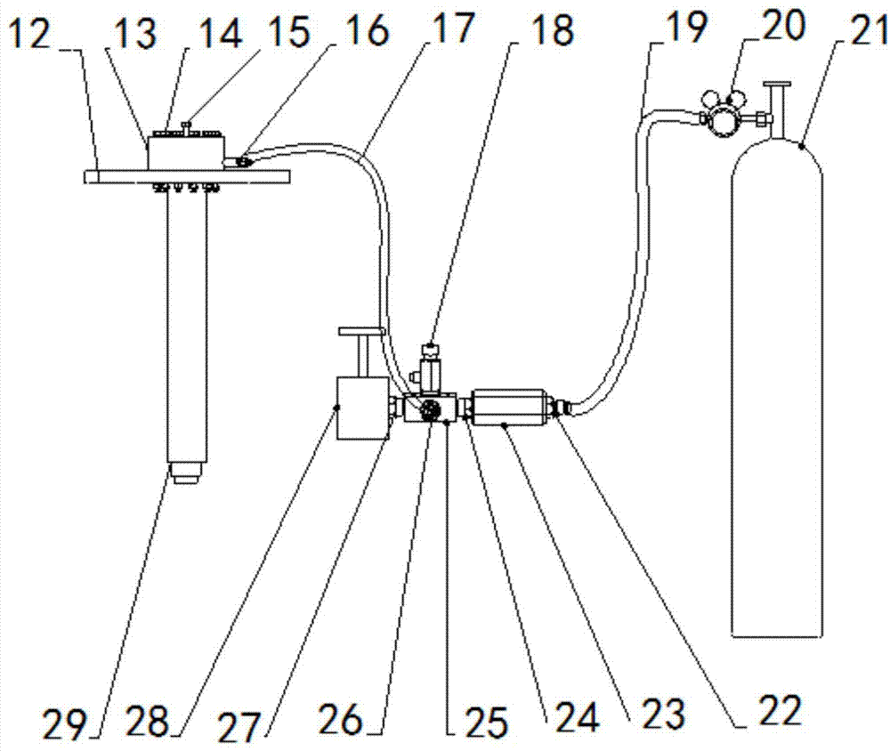
[0016] Embodiment 1: as figure 2 , image 3 As shown, a cylinder pressure stabilization control device, the fixed plate 12 is connected with the cylinder top cover 13 through 12 M16 mounting bolts 14, the gas cylinder air inlet joint 16 is connected with the air inlet of the cylinder, and the air cylinder air intake joint 16 passes through the first A rubber hose 17 is connected to the second transition joint 26, the second transition joint 26 is installed on the four-way manifold 25, and the overflow valve 18, the first transition joint 24 and the second transition joint 26 are respectively installed on the four-way manifold 25 , the stop valve 28 is connected to the second transition joint 27, the one-way valve 23 is connected to the fourth transition joint 24, the second rubber hose 19 is connected to the one-way valve 23 through the third transition joint 22, and the outlet of the pressure reducing valve 20 is connected to the second transition joint 24. The rubber hose ...

Embodiment 2

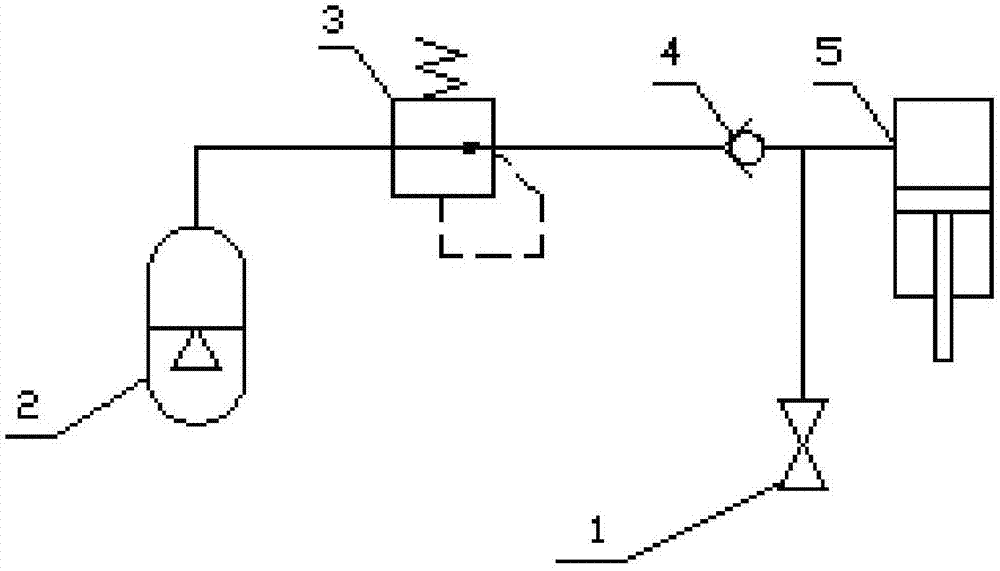
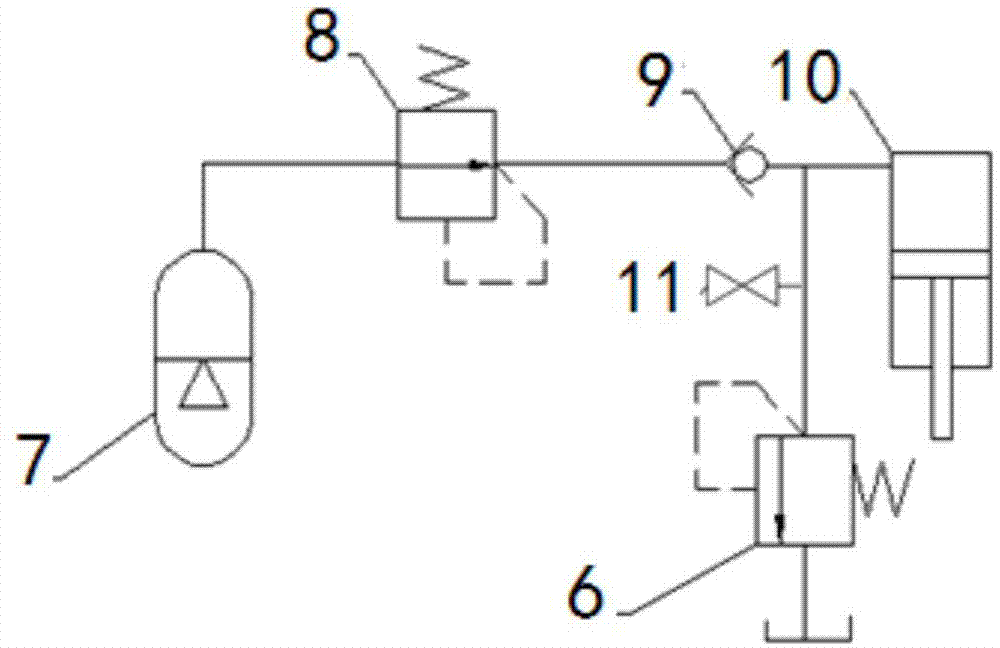
[0017] Embodiment 2: as figure 2 , image 3 As shown, the principle of the cylinder pressure stabilization control device is as follows figure 2 Shown, a cylinder pressure stabilization control device, the pressure reducing valve 8 is installed at the outlet of the nitrogen cylinder, used to adjust the inflation pressure in the cylinder and realize automatic inflation when the air pressure in the cylinder decreases; the outlet of the pressure reducing valve 8 is connected with the single The one-way valve 9 is connected through a pipeline, and the one-way valve 9 protects the pressure reducing valve 8 and the nitrogen cylinder 7; the cylinder 10 is connected with the one-way valve 9 through a pipeline, and the stop valve 11 and the gas overflow valve 6 are respectively connected in parallel with the one-way valve. 9 and the pipeline connected to the cylinder 10.

[0018] A method of using a cylinder pressure stabilization control device, by adjusting the setting value of t...


PUM


Abstract

The invention discloses a cylinder pressure stable control device and a use method and belongs to the technical field of petroleum and seismic exploration equipment. A fixed plate is connected with a cylinder top cover through 12 M16 mounting bolts, the inlet connector of a gas bottle is connected with a gas inlet of a cylinder, the inlet connector of the gas bottle is connected with a second transition connector through a first rubber tube, the second transition connector is mounted on a four-way manifold, an overflow valve, a first transition connector and the second transition connector are respectively mounted on the four-way manifold, a stop valve is connected with the second transition connector, a check valve is connected with a fourth transition connector, a second rubber tube is connected with the check valve through a third transition connector, the outlet of a pressure reducing valve is connected with the second rubber tube, and the gas inlet of the pressure reducing valve is connected with a nitrogen bottle; the parallel connection of the check valve, the gas inlet connector of the cylinder, the stop valve and a gas overflow valve is realized through the four-way manifold. The cylinder pressure stable control device and the use method realize the attenuation of gas under the same pressure state, ensure the consistency on the pressure attenuation of the gas and reduce the gas pressure difference in each time.

Description

technical field [0001] The invention relates to a cylinder pressure stabilization control device and a use method, belonging to the technical field of petroleum seismic exploration equipment. Background technique [0002] At present, the heavy hammer pulse source at home and abroad mainly adopts the structure driven by cylinder compression energy storage, and its principle is as follows: figure 1 As shown. The nitrogen cylinder 2 serves as the inflation pressure source of the cylinder 5; the pre-charge gas pressure in the cylinder is controlled by the pressure reducing valve 3, which can realize different excitation energy requirements; the one-way valve 4 plays a protective role for the pressure reducing valve, and the stop valve 1 Used as an exhaust valve when the system needs to be maintained. [0003] Due to the instability of the compressed state of the gas and the influence of the work done by the gas on the weight on the state of the gas, the pressure of the gas chan...

Claims


Application Information

Patent Timeline
Patent Type & Authority Applications(China)
IPC IPC(8): G01V1/137
Inventor 张永刚邓东王永芳
Owner BGP OF CHINA NAT GASOLINEEUM CORP
Why Eureka
Try Eureka