
Transit trolley for components and parts

A technology of parts and trolleys, applied in trolleys, motor vehicles, multi-axis trolleys, etc., can solve problems such as deformation of auxiliary equipment, inability to meet the versatility of other parts, and bumps on the surface of the body-in-white

Inactive Publication Date: 2014-02-12
WUHU SHUNCHANG AUTO PARTS
View PDF6 Cites 2 Cited by
  • Summary
  • Abstract
  • Description
  • Claims
  • Application Information

AI Technical Summary

Problems solved by technology

[0002] The production workshop needs to handle different parts, especially the automobile main engine factories, which involve many processes and parts. For example, painting aids must be used in the painting process, and the types of automobile painting aids Too many and large amount of use make the storage of all kinds of assistive devices very messy on site, and during the transportation of a large number of assistive devices, due to the upward and downward extrusion, deformation of the assistive devices often occurs after extrusion, and even directly leads to problems such as the scrapping of the assistive devices
Similarly, when the body-in-white is moved from one station to another, there is also a transportation problem. If the transportation is improper, it will cause defects such as bumps on the surface of the body-in-white, which will affect the quality of the body-in-white.
The existing transfer tool has a single function, and there is a problem of versatility in the transfer of different models. For example, it cannot meet the transfer of various types of body-in-white, let alone the transfer of other parts. increase cost

Method used


Image

  • Transit trolley for components and parts
  • Transit trolley for components and parts
  • Transit trolley for components and parts

Examples


Embodiment Construction

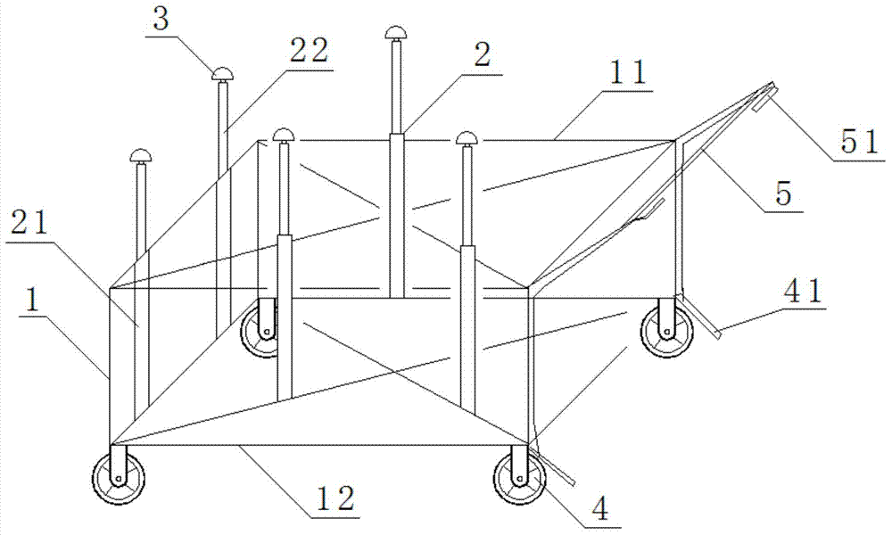
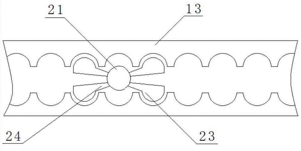
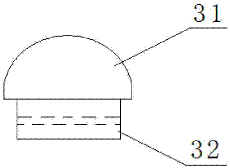
[0016] Figure 1-3 It is a structural schematic diagram of the transfer trolley used for parts in the present invention, figure 2 It is a structural schematic diagram of the cooperation between the guide rail and the outer sleeve, image 3 Schematic diagram of the support pad structure. Depend on Figure 1-Figure 3 It can be seen from the combination that this kind of transfer trolley for parts includes a frame 1, and the frame includes an upper frame 11 and a lower frame 12, and the upper frame 11 and the lower frame 12 are connected together by longitudinal support bars located at four corners. The four sides and two diagonals corresponding to the upper frame 11 and the lower frame 12 are respectively provided with a plurality of uprights 2 penetrating the frame 1. The uprights 2 include an outer sleeve 21 and an inner sleeve whose end is located inside the outer sleeve 21. sleeve 22, and the size of the overlapping portion of the inner sleeve 22 and the outer sleeve 21 ...


PUM


Abstract

The invention discloses a transit trolley for components and parts. The transit trolley comprises a frame, wherein the frame comprises an upper frame and a lower frame. The upper frame and the lower frame are connected together through vertical support rods positioned on four corners, and a plurality of stand columns penetrating through the frame are respectively arranged on the four corresponding edges and the two corresponding diagonal lines of the upper frame and the lower frame. Each stand column comprises an outer sleeve and an inner sleeve of which one end is positioned in the outer sleeve, and the size of the overlap section of the inner sleeve and the outer sleeve is adjustable. The top end of the inner sleeve is a hollow structure, and a fixed hole is formed in the periphery of the hollow structure. A support pad for supporting components and parts to be transferred is installed in the hollow structure. The outer sleeve of which the position can freely move and the inner sleeve of which the height can be freely regulated are arranged on the transit trolley for components and parts, so that the outer sleeve and the inner sleeve can be regulated according to the sizes and shapes of the components and parts to be transferred, and therefore the transit universality requirements of different components and parts are met.

Description

technical field [0001] The invention relates to a transfer trolley for spare parts. Background technique [0002] The production workshop needs to handle different parts, especially the automobile main engine factories, which involve many processes and parts. For example, painting aids must be used in the painting process, and the types of automobile painting aids Too many and large quantities lead to messy storage of all kinds of assistive devices on site, and a large number of assistive devices are often squeezed up and down during transportation, often deformed after being squeezed, and even directly lead to problems such as scrapping of assistive devices. Similarly, when the body-in-white is moved from one station to another, there is also a transportation problem. If the transportation is not done properly, defects such as bumps will occur on the surface of the body-in-white, which will affect the quality of the body-in-white. The existing transfer tool has a single fu...

Claims


Application Information

Patent Timeline
Patent Type & Authority Applications(China)
IPC IPC(8): B62B3/02
Inventor 周军刘萍方崇武童培易唐萍刘国莉晋启云
Owner WUHU SHUNCHANG AUTO PARTS
Learn More