A lithium battery charging protection circuit

A technology for charging protection and lithium batteries, applied in safety/protection circuits, emergency protection circuit devices, measuring electricity, etc., can solve problems such as fuzzy concepts and misoperation of lithium battery control systems, avoid battery quality damage, and improve work efficiency , the effect of prolonging the service life

Active Publication Date: 2016-03-02
HUIZHOU BLUEWAY ELECTRONICS
View PDF3 Cites 0 Cited by
  • Summary
  • Abstract
  • Description
  • Claims
  • Application Information

AI Technical Summary

Problems solved by technology

Because most of the base station maintenance personnel and home users have a vague concept of the lithium battery control system and do not understand the technology in this field, various misoperations will occur during installation and use

Method used


Image

  • A lithium battery charging protection circuit
  • A lithium battery charging protection circuit
  • A lithium battery charging protection circuit

Examples


Embodiment 1

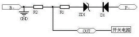
[0012] Embodiment one: as attached image 3 shown. The lithium battery charging protection circuit disclosed in this embodiment includes a switch circuit connected between the negative terminal B- of the rechargeable battery and the negative terminal P- of the charger, and a charging signal detection circuit connected to the switch circuit for controlling the on-off of the switch circuit. The charging signal detection circuit includes a diode D1, a voltage regulator tube ZD1, a resistor R1, and a resistor R2 connected in series between the negative terminal P- of the charger and the negative B- of the rechargeable battery in sequence; the anode of the diode D1 is connected to the negative terminal P- of the charger. , the cathode of diode D1 is connected to the regulator end of regulator tube ZD1, and the other end of regulator tube ZD1 is connected to resistor R1 and resistor R2 in turn, and the connection point of resistor R1 and resistor R2 is used as the output terminal OU...

Embodiment 2

[0014] Embodiment two: as attached Figure 4 shown. The lithium battery charging protection circuit disclosed in this embodiment is an improvement on the basis of the first embodiment. Specifically, this embodiment includes a switch circuit connected between the negative terminal B- of the rechargeable battery and the negative terminal P- of the charger, and a charging signal detection circuit connected to the switch circuit for controlling the on-off of the switch circuit. The signal detection circuit includes a diode D1, a voltage regulator tube ZD1, a resistor R1, and a resistor R2 connected in series between the negative terminal P- of the charger and the negative B- of the rechargeable battery in sequence; the anode of the diode D1 is connected to the negative terminal P- of the charger, and the diode D1 The negative pole of D1 is connected to the regulator end of the voltage regulator tube ZD1, and the other end of the voltage regulator tube ZD1 is connected to the resi...


PUM


Abstract

A charging protection circuit for a lithium battery, comprising a switching circuit and a charging signal detection circuit, which is used for controlling the on and off of the switching circuit, wherein the switching circuit comprises a MOS tube Q1 and a MOS tube Q2; the charging signal detection circuit comprises a diode D1, a voltage regulator tube ZD1, a resistor R1 and a resistor R2 which are connected in series between a negative terminal (P-)of a charger and a negative electrode (B-) of a rechargeable battery successively; a positive electrode of the diode D1 is connected to the negative terminal (P-) of the charger; and a negative electrode of the diode D1 is connected to the voltage regulation end of the voltage regulator tube ZD1; the other end of the voltage regulator tube ZD1 is connected to the resistor R1 and the resistor R2 successively; and as an output end (OUT) of the charging signal detection circuit, a connection point of the resistor R1 and the resistor R2 is connected to a control end of the switching circuit. The protection circuit can distinguish whether the charger is correctly connected to a battery or not, thereby avoiding damage to battery quality caused by the incorrect connection of a circuit, prolonging the service life of the battery, improving the working efficiency, protecting the environment and saving energy.

Description

technical field [0001] The invention relates to the field of battery detection and protection, in particular to a lithium battery charging protection circuit. Background technique [0002] With the gradual promotion of the concept of environmental protection, lithium energy storage batteries, as a new type of environmentally friendly energy that is promoted around the world, are no longer limited to the application of power supplies for small and medium-sized mobile devices such as mobile phones, MP3, MP4, digital cameras, and notebooks, and are gradually replacing Lead-acid batteries become the power source of electric tools, electric motorcycles, electric bicycles and other tools. The country is also promoting lithium batteries to communication base stations, using high-power lithium batteries as energy storage power sources for communication base stations. At the same time, with new energy entering the civilian market, many households have installed rooftop photovoltaic ...

Claims


Application Information

Patent Timeline
Patent Type & Authority Patents(China)
IPC IPC(8): H02H7/18H02H11/00G01R31/02
CPCH02H7/18H02H11/003H02J7/0034
Inventor 杨宇帮
Owner HUIZHOU BLUEWAY ELECTRONICS
Why Eureka
Try Eureka