
Differential positioning method for directly-launched signal differential pseudo satellite and satellite and ground combination

A differential positioning and pseudolite technology, applied in the field of satellite navigation ground-based local area enhancement, can solve the problems of insufficient number of visible navigation satellites, poor geometric distribution of constellations, and low vertical positioning accuracy

Active Publication Date: 2014-02-12
NO 54 INST OF CHINA ELECTRONICS SCI & TECH GRP
View PDF2 Cites 7 Cited by
  • Summary
  • Abstract
  • Description
  • Claims
  • Application Information

AI Technical Summary

Problems solved by technology

[0003] The purpose of the present invention is to design a direct signal differential pseudolite aimed at the defects of insufficient number of visible navigation satellites, poor constellation geometric distribution, and low vertical positioning accuracy caused by satellite navigation systems in special geographical environments or application environments. system, a differential positioning method of direct signal differential pseudolite and satellite-ground combination is proposed to improve the geometric distribution of the satellite navigation system, increase the number of navigation stars, and improve the positioning accuracy

Method used


Image

  • Differential positioning method for directly-launched signal differential pseudo satellite and satellite and ground combination
  • Differential positioning method for directly-launched signal differential pseudo satellite and satellite and ground combination
  • Differential positioning method for directly-launched signal differential pseudo satellite and satellite and ground combination

Examples


Embodiment Construction

[0026] Below in conjunction with specific embodiment and accompanying drawing, the present invention will be further described:

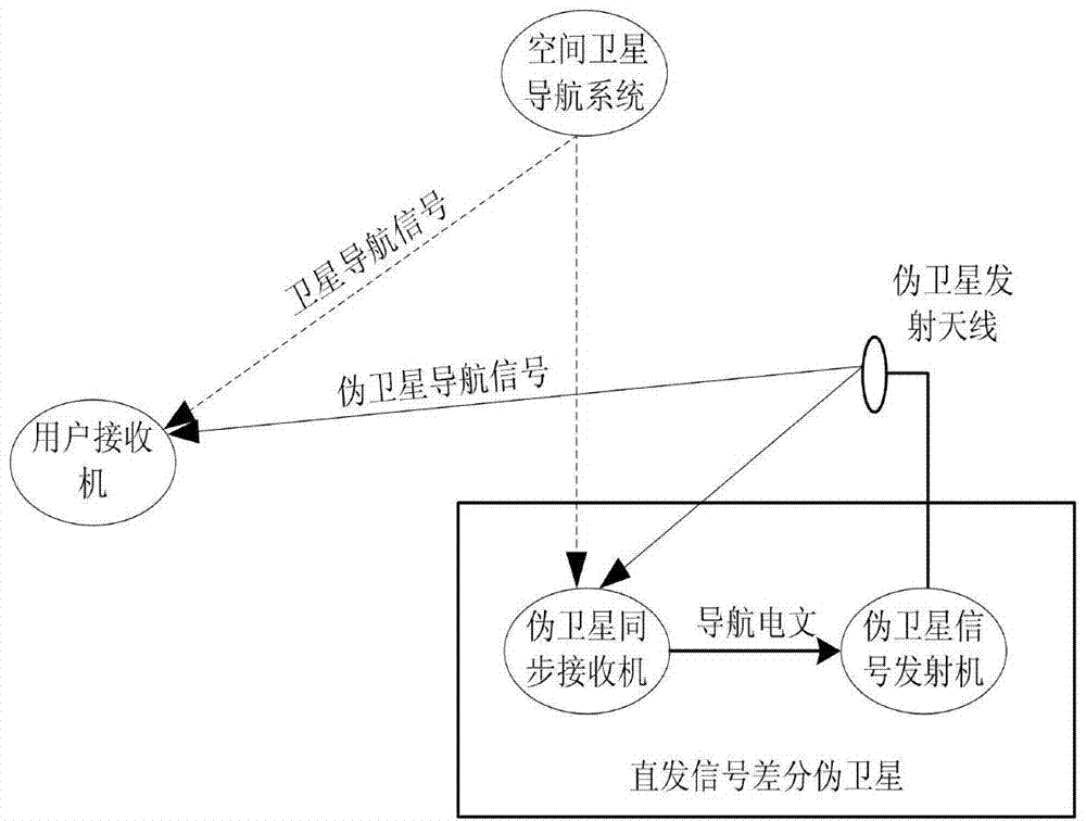
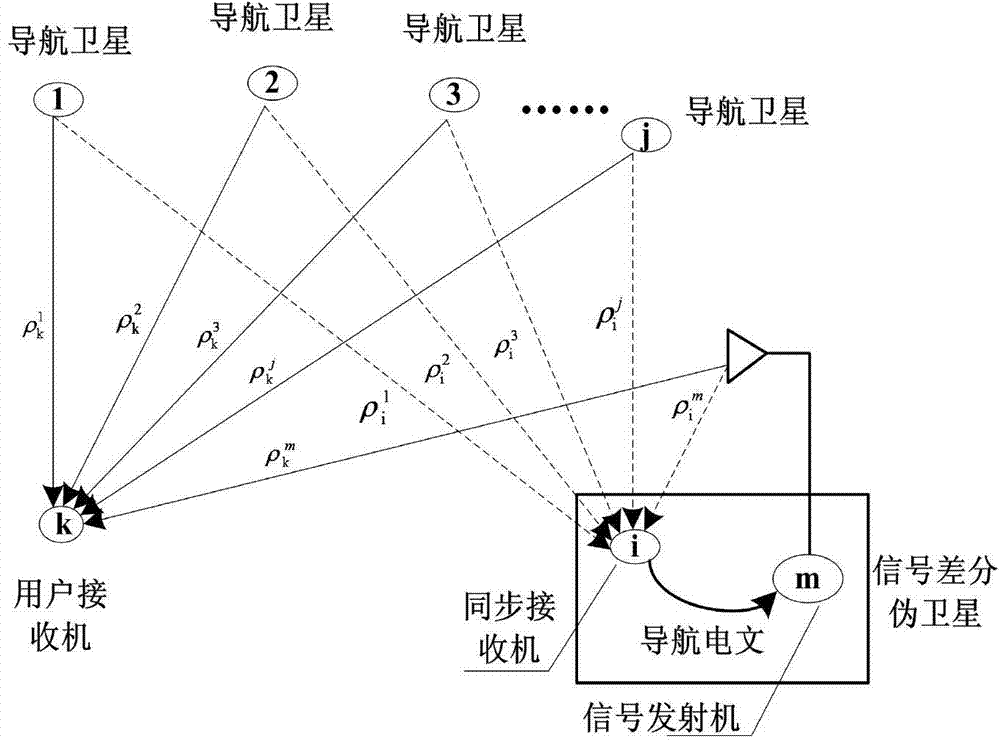
[0027] ① Build a direct signal differential pseudolite system, including a direct signal differential pseudolite, a user receiver and a space satellite navigation system; the signal transmitter of the pseudolite generates a positioning differential signal of the pseudolite with the trigger pulse as the time reference;

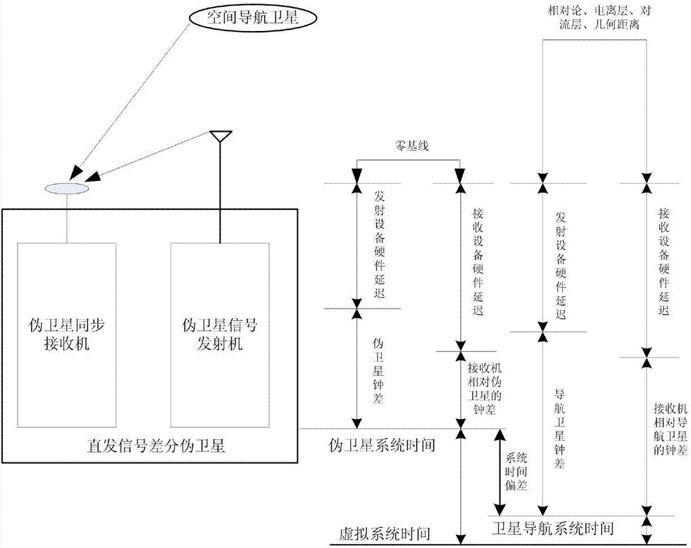
[0028] ② The synchronous receiver of the pseudolite simultaneously receives the signal transmitted by the pseudolite signal transmitter and the signal transmitted by the space satellite navigation system. The satellite-ground synchronous clock difference between the satellite and the space satellite navigation system arranges the satellite-ground synchronous clock difference into a navigation message, and sends the navigation message to the pseudolite signal transmitter in real time; the pseudolite transmitter broadcasts the navigatio...


PUM


Abstract

The intervention discloses a differential positioning method for a directly-launched signal differential pseudo satellite and satellite and ground combination. The method includes the steps that firstly, a signal transmitter of the pseudo satellite generates positioning signals with trigger pulses as reference, and a synchronous receiver and a user receiver receive the signals and satellite signals of a space satellite navigation system; secondly, the satellite and ground synchronization clock difference between the pseudo satellite and the space satellite navigation system is acquired by the synchronous receiver of the pseudo satellite through calculation according to a measured distance measuring value of the pseudo satellite and a measured distance measuring value of the space satellite navigation system, and the satellite and ground synchronization clock difference is edited into a navigation message and transmitted to the signal transmitter of the pseudo satellite to be broadcasted; thirdly, the user receiver corrects the satellite and ground synchronization clock difference broadcasted by the signal transmitter of the pseudo satellite into a space satellite navigation measuring equation to obtain a corrected space satellite navigation measuring equation; fourthly, the user receiver combines the corrected space satellite navigation measuring equation and a pseudo satellite measuring equation to establish a measuring equation set, and then differential positioning for the satellite and ground combination is carried out through the least square method.

Description

technical field [0001] The invention relates to the technical field of satellite navigation ground-based local area enhancement, in particular to a differential positioning method of direct signal differential pseudolite and satellite-ground combination. Background technique [0002] At present, the pseudolite system is an important ground-based augmentation device for satellite navigation, mainly including two types: direct-transmission pseudolite and reflective synchronous pseudolite. The direct-sending pseudolite is to directly transmit the navigation signal similar to the space satellite. The user receiver only uses it as a ground satellite, which can only improve the geometric distribution of the satellite constellation, reduce the vertical precision factor VDOP and increase the availability of the navigation system. Its disadvantage is that it does not have the function of eliminating the error of the satellite clock, the error of the ionosphere, the error of the tropo...

Claims


Application Information

Patent Timeline
Patent Type & Authority Applications(China)
IPC IPC(8): G01S19/46
CPCG01S19/07G01S19/41G01S19/46
Inventor 甘兴利王缚鹏赵娓魏海涛晁磊张骞张志新
Owner NO 54 INST OF CHINA ELECTRONICS SCI & TECH GRP
Learn More