
Automatic aligning device

An automatic alignment and assembly technology, applied in the direction of coupling devices, measuring devices, measuring device casings, etc., can solve the problems of signal pin misalignment, collision, failure to transmit detection signals smoothly, and maintenance costs and time.

Inactive Publication Date: 2014-02-12
WISTRON CORP
View PDF14 Cites 12 Cited by
  • Summary
  • Abstract
  • Description
  • Claims
  • Application Information

AI Technical Summary

Problems solved by technology

[0003] In the above-mentioned process of connecting the signal pins to the connection ports of the electronic device under test, if the signal pins are not connected to the corresponding connection ports accurately, then the signal pins cannot be smoothly connected to the corresponding connection ports. If the corresponding connection port is correctly combined, the detection signal cannot be transmitted smoothly, resulting in the failure of the detection process; in severe cases, the signal pin will collide with the corresponding connection port, causing the signal pin to break or the connection port to be damaged, which will cost maintenance funds and time

Method used


Image

  • Automatic aligning device
  • Automatic aligning device
  • Automatic aligning device

Examples


Embodiment Construction

[0042] The foregoing and other technical content, features and effects of the present invention will be clearly presented in the following detailed description of a preferred embodiment with reference to the accompanying drawings.

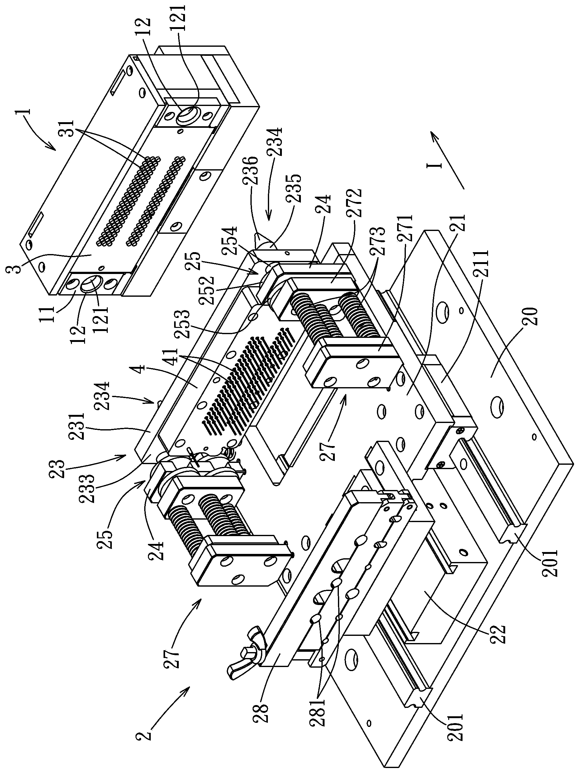
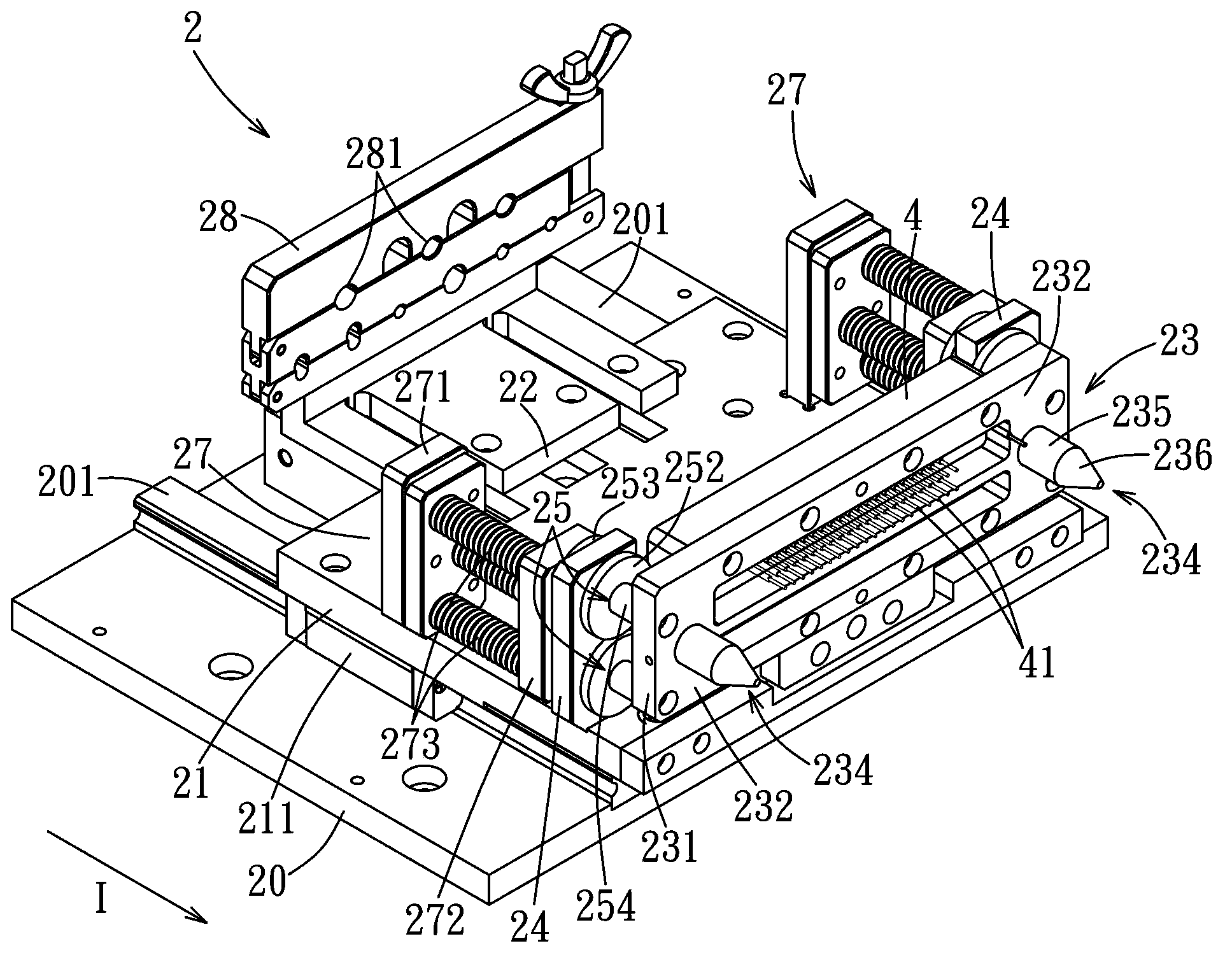
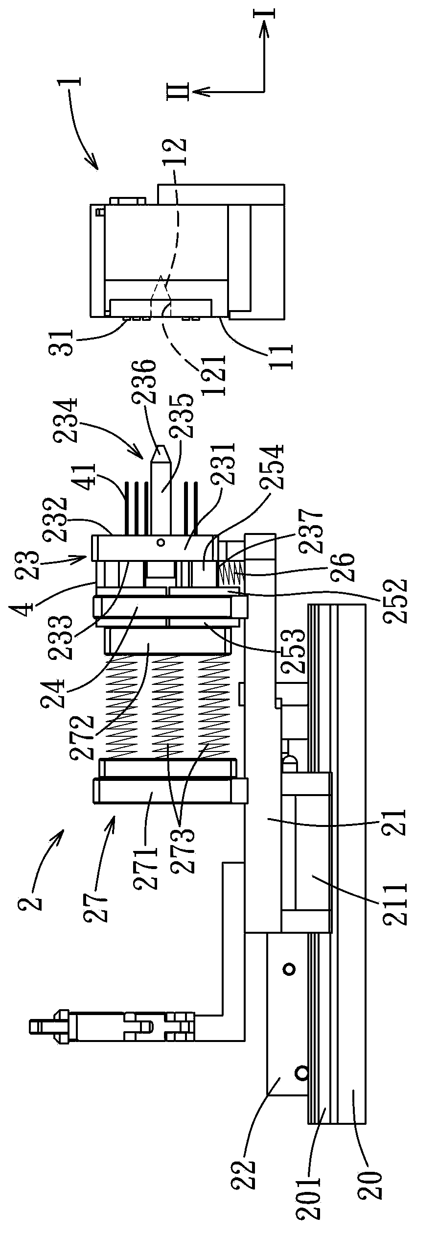
[0043] Refer to Figure 1 to Figure 4 , Is a preferred embodiment of the automatic positioning device of the present invention, which is suitable for aligning a plurality of first components 31 of a first object 3 to a plurality of second components 41 of a second object 4. In this embodiment In the example, the first object 3 is an electronic device, and each first component 31 is a signal connection port. The second object 4 is a dial, the second components 41 are signal pins that penetrate and are fixed to the dial, and each second component 41 can be inserted into the corresponding first component 31 of the first object 3. The automatic alignment device includes a first alignment mechanism 1 and a second alignment mechanism 2. The first alignmen...


PUM


Abstract

Provided is an automatic aligning device which is suitable for making multiple first components of a first object to be respectively aligned with multiple second components of a second object. The automatic aligning device comprises a first aligning mechanism and a second aligning mechanism. The first aligning mechanism can bear the first object and comprises a rear side surface and a correcting groove. The second aligning mechanism is arranged on the rear side of the first aligning mechanism and comprises a pedestal, a supporting frame, a bearing piece, two rear supporting plates and two connecting pieces. The supporting frame is slidably connected with the pedestal. The bearing piece is provided with a bearing front plate and at least one aligning guiding post. Each rear supporting plate is arranged on the supporting frame so that at least one through groove is formed. Each connecting piece is connected with the rear end surface of the bearing front plate and provided with a shaft part, a first clamping part and a second clamping part so that the rear supporting plates are clamped. The supporting frame can move between an initial position and an aligning position in a reciprocating way. The aligning guiding post is separated from the correcting groove when the supporting frame is at the initial position, and the aligning guiding post is worn inside the correcting groove when the supporting frame is at the aligning position. Two components can be accurately aligned and connected by the automatic aligning device.

Description

Technical field [0001] The invention relates to an alignment device, in particular to an automatic alignment device. Background technique [0002] Generally, when a machine used to detect electronic equipment is in use, multiple signal pins installed on the machine are used to electrically connect to multiple connection ports of the electronic equipment under test, and the signal pins sent by the machine The test signal input corresponds to the connection port of the electrical connection, and the response of the electronic device after receiving the test signal is used to understand whether the connection port of the electronic device functions normally. [0003] In the above process of connecting the signal pins to the connection ports of the electronic device under test, if the signal pins are not accurately connected to the corresponding connection ports, the signal pins cannot be smoothly connected to the corresponding connection ports. If the corresponding connection ports a...

Claims


Application Information

Patent Timeline
Patent Type & Authority Applications(China)
IPC IPC(8): H01R43/26
CPCG01R1/04H01R13/6315G01R1/0416H01R43/26
Inventor 郭建红
Owner WISTRON CORP
Learn More