
Printed slot-type directional antenna, and system comprising an array of a plurality of printed slot-type directional antennas

An antenna system, directional antenna technology, applied to antenna arrays, individually powered antenna arrays, combinations of antenna elements with different polarization directions, etc.

Inactive Publication Date: 2014-02-19
THOMSON LICENSING SA
View PDF8 Cites 10 Cited by
  • Summary
  • Abstract
  • Description
  • Claims
  • Application Information

AI Technical Summary

Problems solved by technology

[0007] However, despite such space optimization, the problem of bulkiness of the aforementioned antenna systems remains relatively significant

Method used


Image

  • Printed slot-type directional antenna, and system comprising an array of a plurality of printed slot-type directional antennas
  • Printed slot-type directional antenna, and system comprising an array of a plurality of printed slot-type directional antennas
  • Printed slot-type directional antenna, and system comprising an array of a plurality of printed slot-type directional antennas

Examples


Embodiment Construction

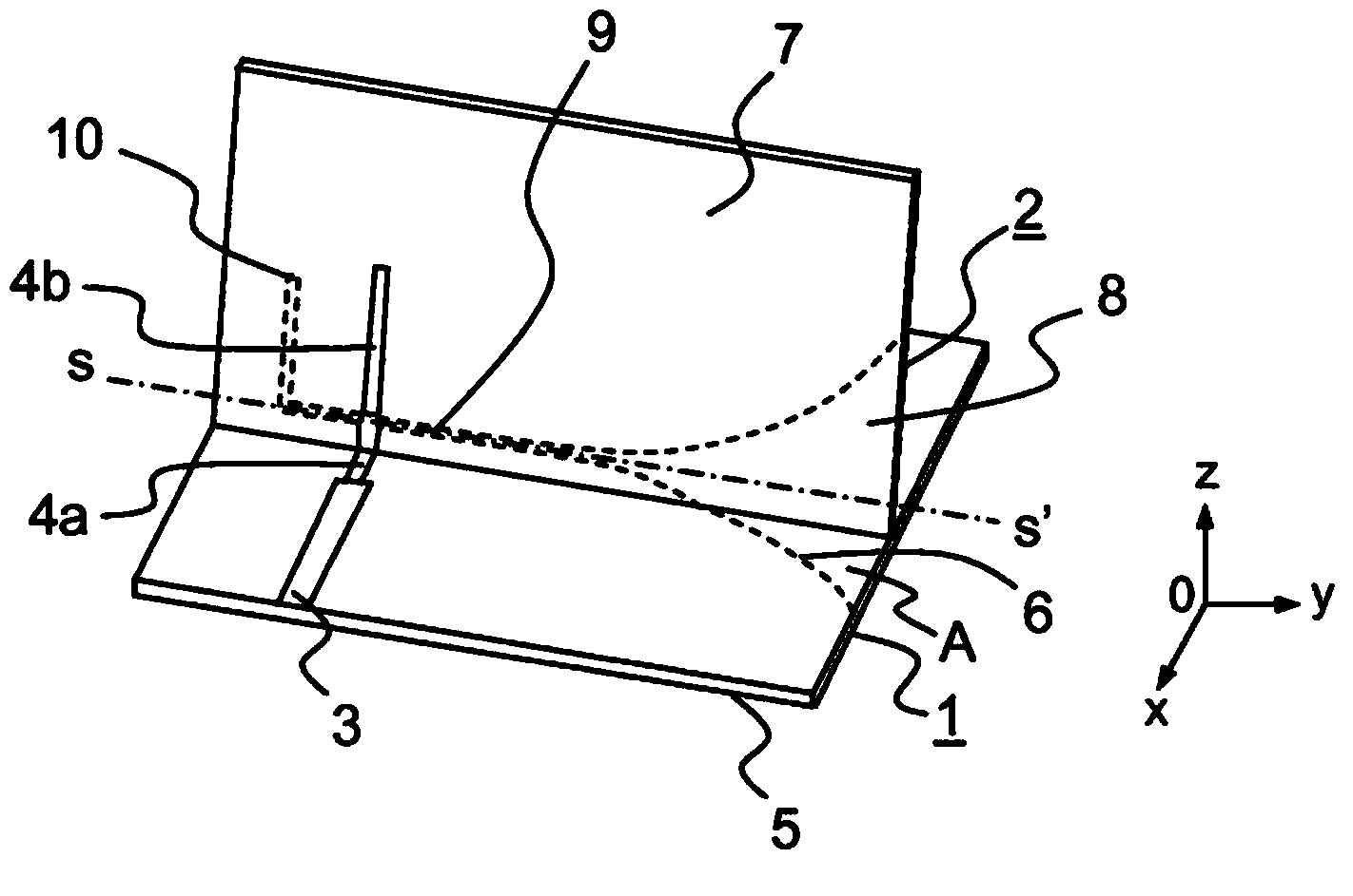
[0029] refer to figure 1 , the printed directional graded slot antenna according to a specific embodiment of the present invention will first be described below. The slot antenna described in this embodiment is a Vivaldi type antenna. However, it is obvious to those skilled in the art that the present invention can be applied to other types of tapered slot antennas.

[0030] Such as figure 1 As shown in , the antenna according to the invention comprises elements forming a substrate consisting of a first substrate part 1 and a second substrate part 2 arranged perpendicular to each other in the illustrated embodiment. More generally, the two substrate parts 1 and 2 can be folded according to the axis OY and form an angle A between them different from 90°. In general, two substrate parts are formed by independent substrates, and in the description, substrate part and substrate have the same meaning.

[0031] Such as figure 1 As shown in , on the upper surface of the first pa...


PUM


Abstract

The present invention relates to a printed slot-type directional antenna. The invention also relates to antenna systems formed by arranging a plurality of such antennas in an array. The flared printed slot-type directional antenna includes a substrate having a floorplan, in which the slot is etched along a profile having a longitudinal axis, and a line for supplying power to the slot, and is characterized in that the substrate comprises at least one first and one second portion which are folded along an axis that is parallel to said longitudinal axis, and which form an angle A relative to one another.

Description

technical field [0001] The present invention relates to printed directional slot antennas, particularly Vivaldi type antennas. The invention also relates to networking different systems of said printed slot antennas to achieve a compact multi-beam antenna system also capable of orthogonal dual polarization. Background technique [0002] The increasing development of communication systems, especially wireless communication systems, requires the realization of increasingly complex and efficient devices while maintaining the lowest possible manufacturing costs and smallest dimensions. To meet these constraints, MIMO (Multiple Input Multiple Output) technology is increasingly used, which implements the concept of multiple antennas to improve transmission both in terms of bit rate and robustness in environments where interference is clearly dominant performance. The development of these MIMO-type multi-antenna transmission devices has led to the development of directional anten...

Claims


Application Information

Patent Timeline
IPC IPC(8): H01Q13/08H01Q21/20
CPCH01Q21/205H01Q13/10H01Q13/085H01Q13/08H01Q21/20H01Q21/26
Inventor D.洛海因童A.洛齐尔P.米纳德J-F.平托斯
Owner THOMSON LICENSING SA
Learn More