Novel test-tube rack for laboratory

A technology for laboratory and test tube racks, applied in the direction of test tube holders/clamps, etc., can solve problems such as failure to meet requirements, test tubes that cannot be clamped, and cannot be turned upside down

Inactive Publication Date: 2014-03-05
SUZHOU YIDA PURIFICATION LAB EQUIP
View PDF6 Cites 12 Cited by
  • Summary
  • Abstract
  • Description
  • Claims
  • Application Information

AI Technical Summary

Problems solved by technology

[0002] At present, most of the test tube racks used in laboratories such as school teaching and scientific research institutes only play the role of accommodating and positioning test tubes. The test tubes placed on the test tube racks cannot be clamped, let alone turned upside down. When checking the reaction situation of the solution

Method used


Image

  • Novel test-tube rack for laboratory

Examples


Embodiment Construction

[0016] In order to enable those skilled in the art to better understand the solution of the present invention, and to make the above-mentioned purpose, features and advantages of the present invention more obvious and understandable, the present invention will be further described in detail below in conjunction with the embodiments and the accompanying drawings of the embodiments.

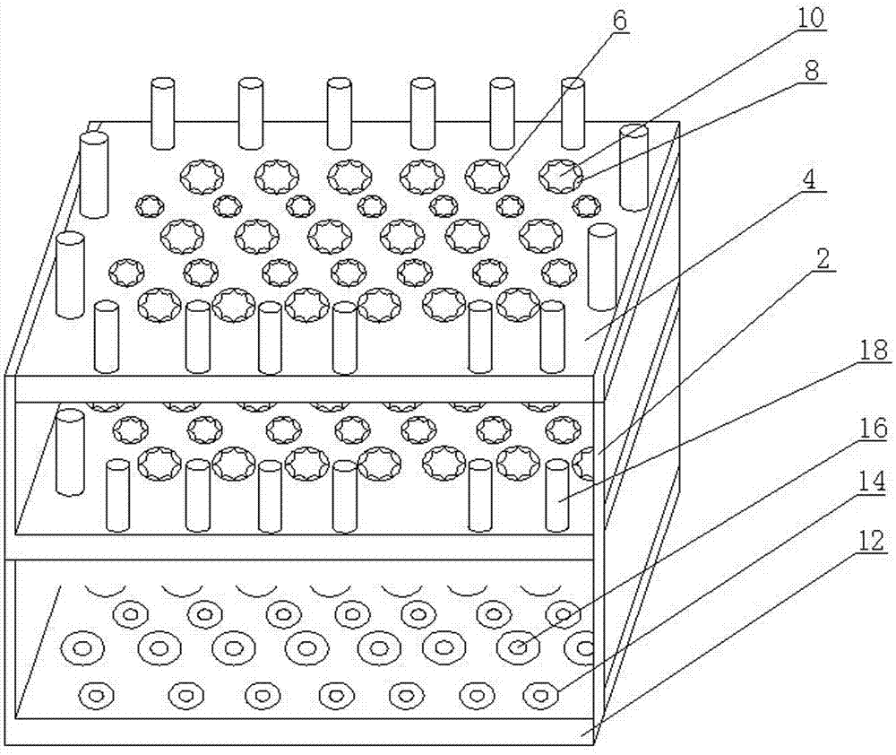
[0017] Such as figure 1 As shown, a new type of test tube rack for laboratory use includes several base plates 4 that are connected and supported by vertical poles 2. For the convenience of description, the present invention selects two base plates 4 for description. Of course, it is not limited to two. Design as three, four or more according to needs, the bottom plate 4 is provided with several positioning holes 6 for accommodating and positioning the test tubes, and several elastic sheets 8 protruding from the inner wall of the positioning holes 6 are provided. , and several shrapnels 8 are conn...


PUM


Abstract

The invention provides a novel test-tube rack for a laboratory. The test-tube rack comprises a plurality of base plates which are overlapped, supported and connected by a vertical rod; a plurality of locating holes for containing and locating test-tubes are formed in the base plates; the test-tube rack is characterized in that a plurality of elastic pieces protruding the inner wall of the locating holes are arranged in the locating holes; the plurality of elastic pieces are connected in an end-to-end manner sequentially to form an elastic washer which is concentric with the locating holes and is used for fixing test-tubes. Because the elastic washer formed in a defining manner by the elastic pieces protruding the inner wall of the locating holes provide certain attractive force and clamping force to the walls of the test-tubes, so that the test rack when being inversed or overturned can attract the test-tubes to enable the test-tubes not to be separated from the test-tube rack, and therefore, the purpose of the novel test-tube rack is realized.

Description

technical field [0001] The invention relates to a test tube rack, in particular to a new laboratory test tube rack which can absorb test tubes when the test tube rack is turned upside down or overturned so that the test tubes will not fall out. Background technique [0002] At present, most of the test tube racks used in laboratories such as school teaching and scientific research institutes only play the role of accommodating and positioning test tubes. The test tubes placed on the test tube racks cannot be clamped, let alone turned upside down. When checking the reaction situation of the solution in the test tube in the low-speed automatic turning instrument, the current test tube rack just cannot meet the requirements. Therefore, the purpose of the present invention is to provide a new type of test tube rack, so that the test tube rack can absorb Hold the test tube so that the test tube does not come out of the test tube rack. Contents of the invention [0003] In orde...

Claims


Application Information

Patent Timeline
IPC IPC(8): B01L9/06
Inventor 周树雄
Owner SUZHOU YIDA PURIFICATION LAB EQUIP
Why Eureka
Try Eureka