
Automatic grabbing mechanism

A grasping mechanism and automatic technology, applied in the direction of manipulators, chucks, manufacturing tools, etc., can solve the problems of low utilization rate of grasping mechanism, low production efficiency, and inability to apply products of different sizes, so as to improve equipment utilization rate, The effect of fast grabbing speed and avoiding product scratches

Active Publication Date: 2014-08-27
BOZHON PRECISION IND TECH CO LTD
View PDF7 Cites 10 Cited by
  • Summary
  • Abstract
  • Description
  • Claims
  • Application Information

AI Technical Summary

Problems solved by technology

[0002] On the production line, sometimes it is necessary to grab the incoming material at a certain position and then move it to another position. The existing equipment is generally realized by a group of grabbing mechanisms, which only grab one product at a time, and the grabbing The product is fixed and cannot be applied to products of different sizes, which makes the utilization rate of the grabbing mechanism low and the production efficiency low

Method used


Image

  • Automatic grabbing mechanism

Examples


Embodiment Construction

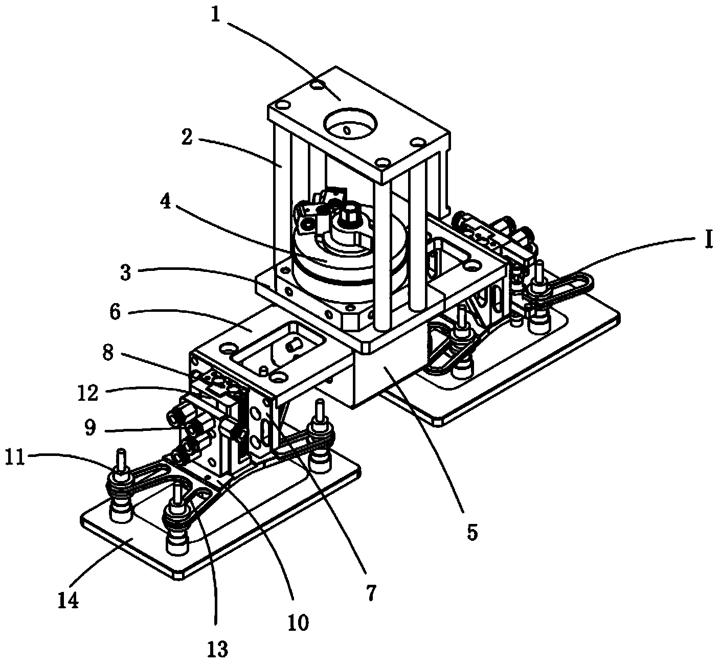
[0015] Examples, see attached figure 1 , an automatic grabbing mechanism, which includes a connecting plate 1, a supporting column 2, a rotating cylinder mounting plate 3, a rotating cylinder 4, a vacuum generator placement box 5 and a grabbing mechanism I. There are four supporting columns, the upper end of which is It is fixedly connected with the connection plate, and the lower end of the support column is fixedly connected with the rotary cylinder mounting plate; the rotary cylinder is mounted on the rotary cylinder mounting plate, and a vacuum generator placement box is installed under the rotary cylinder mounting plate, and the rotary shaft of the rotary cylinder is connected to the The vacuum generator placement boxes are connected together; a set of grasping mechanisms are respectively installed on both sides of the vacuum generator placement box; the two sets of grasping mechanisms can rotate 180°C through the rotating cylinder, and can alternately grasp products.

[...


PUM


Abstract

The invention relates to an automatic grabbing mechanism. The upper end of a supporting stand column of the automatic grabbing mechanism is fixedly connected with a connecting plate, and the lower end of the supporting stand column of the automatic grabbing mechanism is fixedly connected with a rotation air cylinder installing plate. A rotation air cylinder is arranged on the rotation air cylinder installing plate, and a vacuum generator containing box is arranged below the rotation air cylinder installing plate. A rotation shaft of the rotation air cylinder is connected with the vacuum generator containing box. The two sides of the vacuum generator containing box are respectively provided with a set of grabbing mechanism body. A grabbing mechanism installing plate of each grabbing mechanism body is installed on the side portion of the vacuum generator containing box, and the lower portions of the front ends of the grabbing mechanism installing plates are provided with air cylinder installing plates. Sliding table air cylinders are installed on the air cylinder installing plates, and sucker adjusting plates are arranged below sliding table plates of the sliding table air cylinders. Each sucker adjusting plate is provided with four sucker jaws, each sucker jaw is provided with a long groove hole, each long groove hole is provided with a sucker, the position of each sucker can be adjusted, and the suckers can be used for sucking products. The two sets of grabbing mechanism bodies can rotate by 180 degrees through the rotation air cylinder and can grab the products in a mutually alternative mode.

Description

Technical field: [0001] The invention relates to the field of grabbing mechanism equipment, and more specifically relates to an automatic grabbing mechanism that grabs incoming materials at a certain position and then moves to another position. Background technique: [0002] On the production line, sometimes it is necessary to grab the incoming material at a certain position and then move it to another position. The existing equipment is generally realized by a set of grabbing mechanisms, which only grab one product at a time, and the grabbing The product is fixed and cannot be applied to products of different sizes, so that the utilization rate of the grasping mechanism is low and the production efficiency is low. Invention content: [0003] The purpose of the present invention is to provide an automatic grabbing mechanism for the deficiencies of the prior art. The two grabbing mechanisms can rotate 180°C through the rotating cylinder and can be alternated with each other...

Claims


Application Information

Patent Timeline
Patent Type & Authority Applications(China)
IPC IPC(8): B25J15/06
Inventor 吕绍林杨愉强吴小平黄仕波
Owner BOZHON PRECISION IND TECH CO LTD
Learn More