Mechanical unlocking mechanism for emergency situations

An emergency and mechanical technology, applied in the mechanical field, can solve the problems of high cost, easy aging and failure of circuits, etc.

Inactive Publication Date: 2014-03-05
BEIJING UNIV OF TECH
View PDF4 Cites 1 Cited by
  • Summary
  • Abstract
  • Description
  • Claims
  • Application Information

AI Technical Summary

Problems solved by technology

However, electronic door locks have disadvantages suc

Method used


Image

  • Mechanical unlocking mechanism for emergency situations
  • Mechanical unlocking mechanism for emergency situations
  • Mechanical unlocking mechanism for emergency situations

Examples


Embodiment Construction

[0014] to combine Figure 1-Figure 6 The present invention is described further:

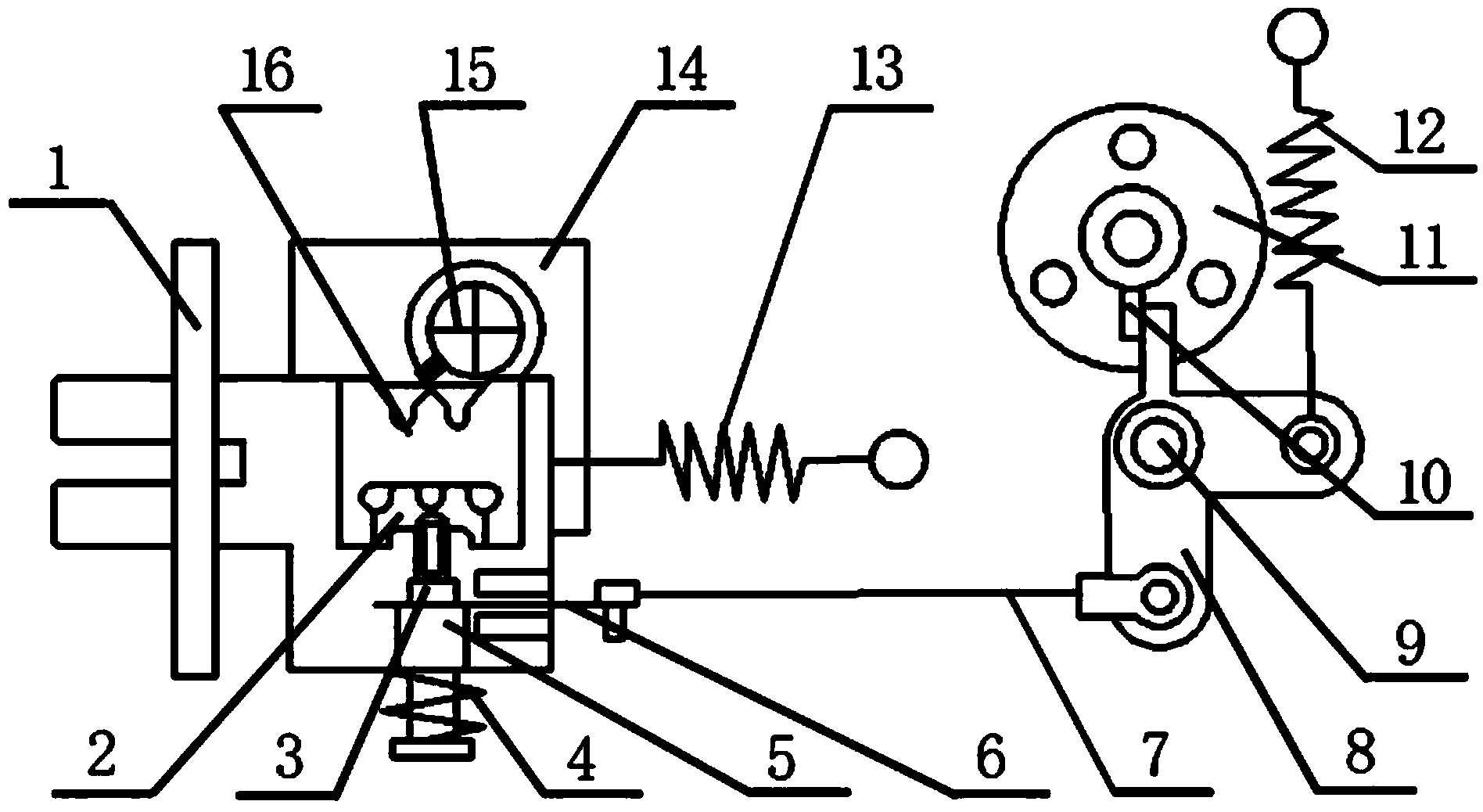
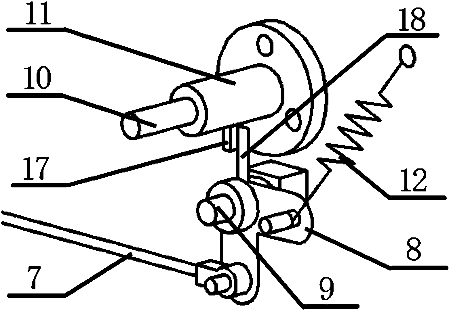
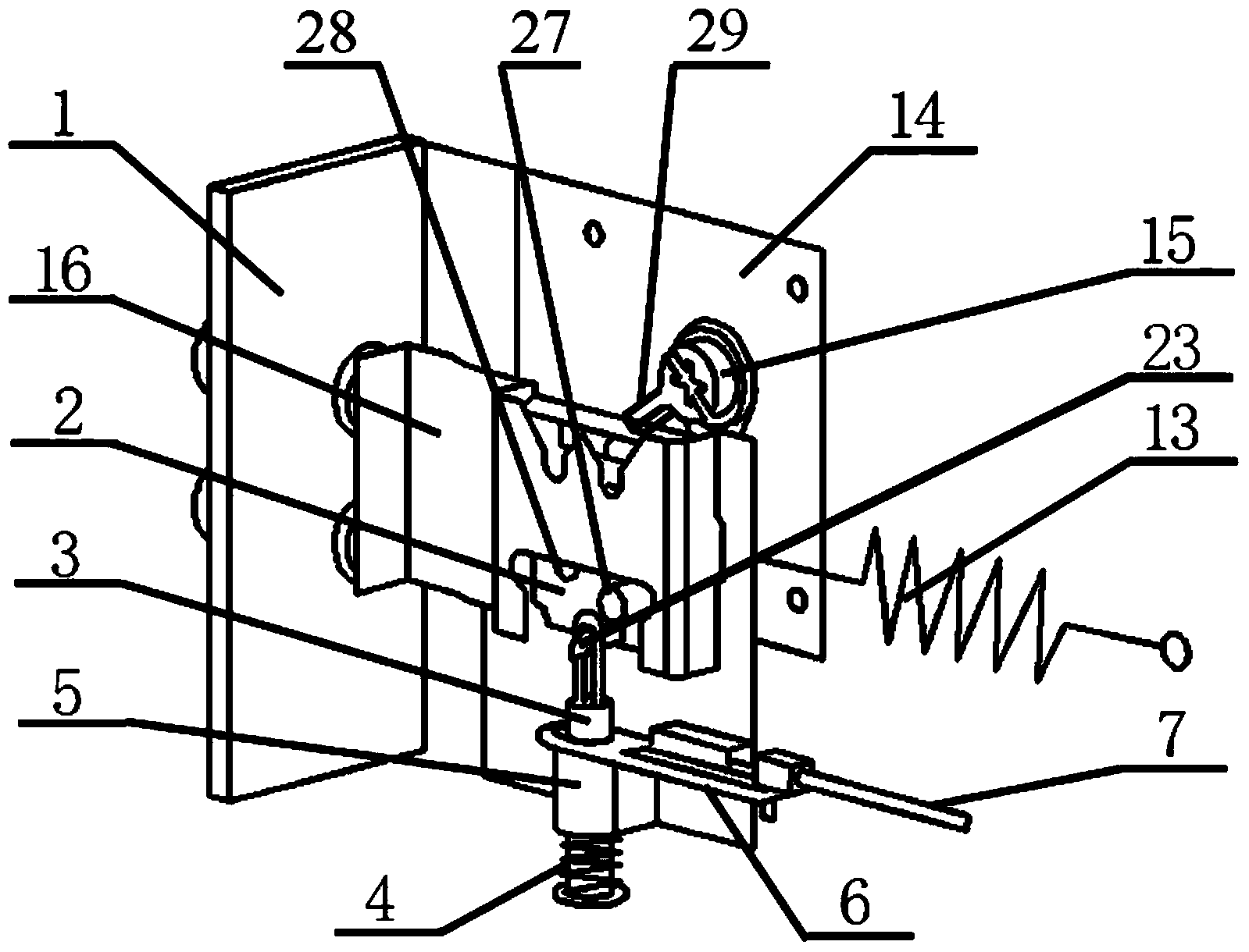
[0015] The mechanical unlocking mechanism in an emergency includes a door body, a trigger mechanism component, and a modified lock component. Both the trigger mechanism assembly and the retrofit lock assembly are secured to the door body. When the trigger block 10 in the trigger mechanism assembly is pressed, the trigger mechanism assembly will be triggered, and the mechanical movement will be transmitted to the refit lock assembly through the connecting rod 7 . The modified lock assembly usually has the function of opening and closing the lock normally, and it will be opened by mechanical trigger in an emergency.

[0016] The trigger mechanism assembly is composed of a trigger block 10 , a linkage base 11 , a trigger power spring 12 , a linkage 8 , a trigger block base 9 and a connecting rod 7 that is pulled laterally. The trigger block 10 can slide up and down in the cylindrical groove on t...


PUM


Abstract

The invention relates to a mechanical unlocking mechanism for emergency situations and belongs to the field of machinery. The mechanical unlocking mechanism applicable to daily house burglary prevention and emergency escape under situations such as earthquakes and fires comprises a door body, a triggering mechanism component and a modified lock component. The mechanical unlocking mechanism is cable of resetting fast, so that the installation personnel can reset the mechanical unlocking mechanism for reuse. The triggering mechanism component and the modified lock component are in linkage, and the lock can be unlocked fast by a one-button triggering function.

Description

technical field [0001] The invention relates to a mechanical unlocking mechanism in an emergency, which belongs to the mechanical field and is applied to daily house anti-theft and emergency escape in earthquakes, fires and the like. Background technique [0002] At present, there are many mechanical locks and electronic locks on the market, and these locks have various functions. However, there are not many products that can be quickly unlocked in response to an emergency. Most of the electronic locks have this emergency function. However, the electronic door lock has disadvantages such as high cost and easy aging and failure of the circuit. And a mechanical unlocking mechanism in an emergency can solve these problems well and avoid disasters. Contents of the invention [0003] The purpose of the present invention is to provide a one-button trigger, so that a common mechanical lock can be quickly and automatically opened in an emergency. [0004] In order to achieve t...

Claims


Application Information

Patent Timeline
IPC IPC(8): E05B65/10E05B17/22
Inventor 李清清余跃庆
Owner BEIJING UNIV OF TECH
Why Eureka
Try Eureka