Supercharge Your Innovation With Domain-Expert AI Agents!

Needleless injector wand assembly

一种组件、腔室的技术,应用在注射器、皮下注射器械、借喷射作用注射器等方向,能够解决装置笨重、小注射器吓人等问题

Active Publication Date: 2014-03-05
IDEE INT R&D
View PDF3 Cites 5 Cited by
  • Summary
  • Abstract
  • Description
  • Claims
  • Application Information

AI Technical Summary

Problems solved by technology

The above syringe has proven to be effective for its intended purpose, which is to give rapid continuous injections, but the device is a bit bulky and not designed for use in restricted areas, such as in the mouth when doing dental work
Also, when doing dental work or injecting into the face or neck, the person receiving the injection will find the small syringe less intimidating than the large gun-shaped device

Method used


Image

  • Needleless injector wand assembly
  • Needleless injector wand assembly
  • Needleless injector wand assembly

Examples


Embodiment Construction

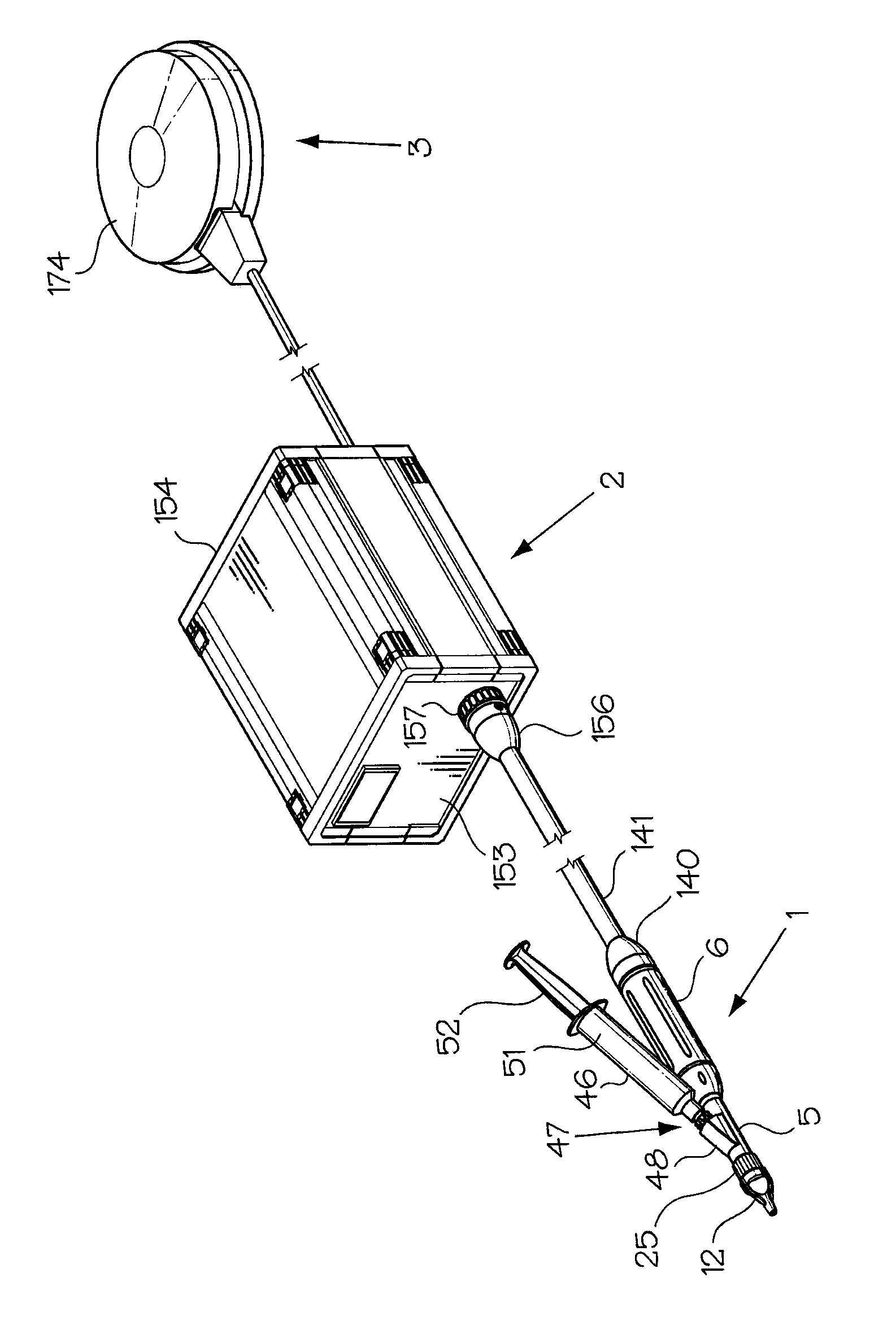
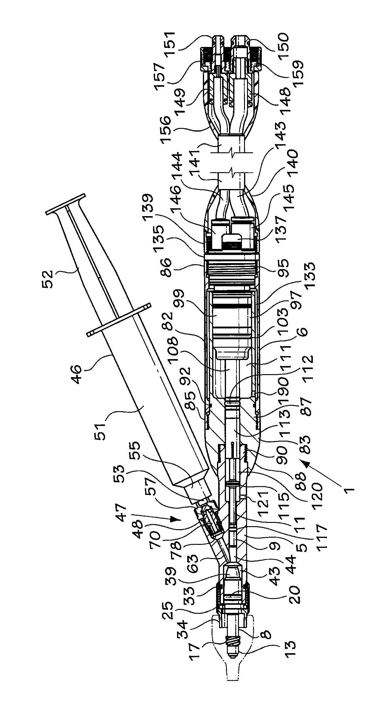
[0026] refer to figure 1 and 2 , the syringe assembly of the present invention comprises a rod, a control unit and a foot pedal actuator, generally denoted 1, 2 and 3 respectively. The rod 1 comprises a tubular barrel delimited by a front part 5 and a rear part 6 respectively. The front barrel portion 5 accommodates a movable nozzle holder 8 and a front end 9 of a plunger 11 .

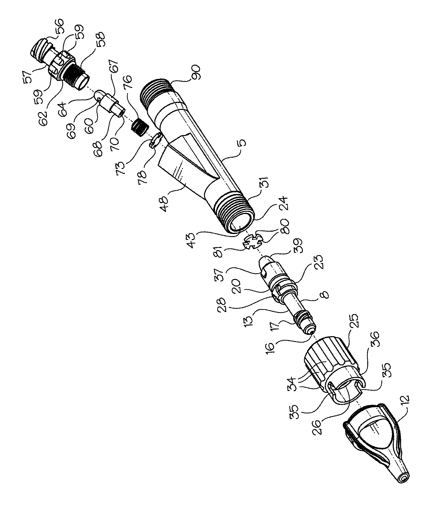
[0027] The nozzle holder 8 and disposable nozzle 12 for the syringe are similar to the same elements described in US Patent No. 7,357,781 issued to the inventor on April 15, 2008. best as Figures 3 to 5 As shown, the nozzle holder 8 comprises a tubular body 13 having a passageway 15 extending therethrough. The liquid passes through the small hole 16 in the front end of the main body 13 ( Figures 3 to 5 )discharge. The thread 17 near the outer end 18 of the main body 13 is used to insert the disposable nozzle 12 ( figure 1 and 3 ) connected to the keeper. The nozzle 12 is sealed on the holder...


PUM


Abstract

A needleless injector syringe includes a tubular barrel containing a first chamber for receiving a liquid, a nozzle on a front end of the barrel, a piston which drives a plunger for discharging the liquid through the nozzle, a second chamber in which the piston slides, a third chamber in fluid communication with the second chamber for receiving gas from said second chamber during forward movement of the piston, and for carrying gas to the second chamber to cause the piston to retract, and a breach plug closing a rear end of the barrel for directing gas under pressure alternately against the rear end of the piston and to the third chamber for driving the piston between the discharge position and a retracted position.

Description

Background of the invention [0001] The present invention relates to needle-free injectors, particularly needle-free injector rod assemblies. [0002] US Patent No. 7,357,781 issued to Karim Menassa on April 15, 2008 discloses a gun-shaped needle-free injector. The patented syringe comprises a barrel for containing a liquid, a nozzle containing an injection orifice closing one end of the barrel, a plunger in the barrel, a piston for driving the plunger towards the nozzle end of the barrel, a piston for holding the The magnet assembly in the rest position and the trigger connected to the valve for permitting gas under pressure to drive the magnet assembly forward against the plunger. The syringe described above has proven effective for its intended purpose, which is to give rapid continuous injections, but the device is somewhat bulky and not designed for use in restricted areas, such as the mouth when doing dental work. Also, when doing dental work or injecting into the face ...

Claims


Application Information

Patent Timeline
Patent Type & Authority Applications(China)
IPC IPC(8): A61M5/30A61M5/31
CPCA61M5/30A61M2005/3128A61M5/204A61M5/2053A61M2209/01A61M5/31A61M5/155
Inventor 卡里姆·梅纳萨莫里斯·梅纳萨亚当·加杜阿
Owner IDEE INT R&D
Features
  • R&D
  • Intellectual Property
  • Life Sciences
  • Materials
  • Tech Scout
  • Unparalleled Data Quality
  • Higher Quality Content
  • 60% Fewer Hallucinations
Learn More