Rotatable fixing clamping sleeve

A clamping and fixing technology, used in workpiece clamping devices, manufacturing tools, etc., can solve the problems of rigid clamping sleeves and inability to rotate freely.

Inactive Publication Date: 2014-03-19
苏州凯欧机械科技有限公司
View PDF5 Cites 0 Cited by
  • Summary
  • Abstract
  • Description
  • Claims
  • Application Information

AI Technical Summary

Problems solved by technology

[0002] At present, in the production process, we need various clamping sleeves, and the clamping sleeves currently used are relatively rigid, and they are all fixed structures and cannot rotate freely.

Method used


Image

  • Rotatable fixing clamping sleeve

Examples


Embodiment Construction

[0010] The present invention will be described in detail below with reference to the accompanying drawings and in combination with embodiments.

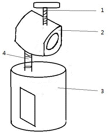
[0011] refer to figure 1 As shown, a rotatable and fixed clamping sleeve includes a bolt 1, a round hole ferrule 2, a stud 3 and a square hole ferrule 4, and the bolt 1 is clamped on the upper end of the round hole ferrule 2 , the round hole ferrule 2 and the square hole ferrule 4 are connected by the stud 3, and the round hole ferrule 2 and the square hole ferrule 4 are rotated to make the stud stud 3 Fix the objects clamped in the round hole ferrule 2 and the square hole ferrule 4 together at both ends.

[0012] Principle of the present invention:

[0013] The present invention adjusts the positions of the round hole chuck 2 and the square hole chuck 4 through the double-ended stud 3, and can fix the positions of the round hole chuck 2 and the square hole chuck 4 together with the bolt 1 by screwing and extruding .

[0014] The...


PUM


Abstract

The invention discloses a rotatable fixing clamping sleeve which comprises a bolt, a circular hole clamping sleeve, a stud and a square hole clamping sleeve. The bolt is clamped at the upper end of the circular hole clamping sleeve, the circular hole clamping sleeve and the square hole clamping sleeve are connected through the stud, and the circular hole clamping sleeve and the square hole clamping sleeve are rotated to enable the two ends of the stud to fix objects which are clamped in the circular hole clamping sleeve and the square hole clamping sleeve. According to the technical scheme, the direction of the circular hole clamping sleeve and the direction of the square hole clamping sleeve can be adjusted at will, two fixed parts are not limited by the same shape.

Description

technical field [0001] The invention relates to a rotatable and fixed clamp sleeve. Background technique [0002] At present, in the production process, we need various clamping sleeves, but the clamping sleeves currently used are relatively rigid, and they are all fixed structures and cannot rotate freely. Contents of the invention [0003] The purpose of the present invention is to overcome the problems existing in the prior art and provide a multifunctional household knife. [0004] In order to achieve the above-mentioned technical purpose and achieve the above-mentioned technical effect, the present invention is realized through the following technical solutions: [0005] A rotatable and fixed clamping sleeve, comprising a bolt 1, a round hole ferrule 2, a stud 3 and a square hole ferrule 4, the bolt 1 is clamped on the upper end of the round hole ferrule 2, the The round hole ferrule 2 and the square hole ferrule 4 are connected with the double-ended stud 3, and the...

Claims


Application Information

Patent Timeline
Patent Type & Authority Applications(China)
IPC IPC(8): B25B11/00
CPCB25B11/00
Inventor 叶邦华
Owner 苏州凯欧机械科技有限公司
Why Eureka
Try Eureka