
Electroplating device that firmly holds the pcb board

A PCB board and electroplating device technology, which is applied in the field of electroplating devices that firmly clamp the PCB board, can solve problems such as easy drop to the tank body, electroplating quality, difficulty in mixing the electroplating solution, and irrelevant PCB board clamping, etc., to achieve enhanced Efficiency, reduction of dead angle, effect of reducing dead angle

Active Publication Date: 2018-06-19
成都展讯通信技术有限公司
View PDF8 Cites 0 Cited by
  • Summary
  • Abstract
  • Description
  • Claims
  • Application Information

AI Technical Summary

Problems solved by technology

[0003] The purpose of the present invention is to provide an electroplating device for stably clamping PCB boards, so as to solve the problem that the electroplating solution for electroplating PCB boards in the prior art is difficult to mix evenly, and the PCB boards are easily dropped into the tank regardless of clamping, and the electroplating quality and efficiency decrease. question

Method used


Image

  • Electroplating device that firmly holds the pcb board
  • Electroplating device that firmly holds the pcb board
  • Electroplating device that firmly holds the pcb board

Examples


Embodiment 1

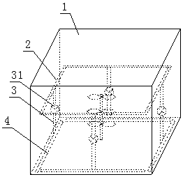
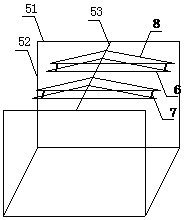
[0034] Figure 1 to Figure 3 An electroplating device 1 for stably clamping a PCB board provided by the present invention includes a tank body 1 and a PCB board clamping device, wherein,

[0035] A liquid spray pipe 4 is provided around the bottom of the tank body 1, a liquid suction pipe 2 near the side wall is provided on the top of the tank body 1, a water pump 3 is provided between the liquid suction pipe 2 and the liquid spray pipe 4, and an inlet 31 of the water pump 3 It is connected with the liquid suction pipe 2, and the outlet of the water pump 3 is connected with the liquid spray pipe 4, and the surfaces of the liquid suction pipe 2 and the liquid spray pipe 4 are all provided with round holes;

[0036] The liquid spray pipe 4 includes a connecting part and a rotating part, the middle part of the connecting part is fixedly connected to the outlet of the water pump 3, and the two ends of the connecting part are respectively connected to the rotating part in rotation;...

Embodiment 2

[0042] Figure 1 to Figure 3 An electroplating device 1 for stably clamping a PCB board provided by the present invention includes a tank body 1 and a PCB board clamping device, wherein,

[0043] The bottom of tank body 1 is provided with liquid spray pipe 4 around, and the upper part of tank body 1 is provided with liquid suction pipe 2 close to the side wall. The liquid suction pipe 2 is connected, the outlet of the water pump 3 is connected with the liquid spray pipe 4, and the surfaces of the liquid suction pipe 2 and the liquid spray pipe 4 are all provided with round holes;

[0044] The liquid spray pipe 4 includes a connecting part and a rotating part, the middle part of the connecting part is fixedly connected to the outlet of the water pump 3, and the two ends of the connecting part are respectively connected to the rotating part in rotation;

[0045] The lower part of the tank body 1 is provided with stirring paddles, and the rotating shafts of the stirring paddles ...

Embodiment 3

[0052] Figure 1 to Figure 3 An electroplating device 1 for stably clamping a PCB board provided by the present invention includes a tank body 1 and a PCB board clamping device, wherein,

[0053] The bottom of tank body 1 is provided with liquid spray pipe 4 around, and the upper part of tank body 1 is provided with liquid suction pipe 2 close to the side wall. The liquid suction pipe 2 is connected, the outlet of the water pump 3 is connected with the liquid spray pipe 4, and the surfaces of the liquid suction pipe 2 and the liquid spray pipe 4 are all provided with round holes;

[0054] The liquid spray pipe 4 includes a connecting part and a rotating part, the middle part of the connecting part is fixedly connected to the outlet of the water pump 3, and the two ends of the connecting part are respectively connected to the rotating part in rotation;

[0055] The lower part of the tank body 1 is provided with stirring paddles, and the rotating shafts of the stirring paddles ...


PUM


Abstract

The invention discloses an electroplating device stably clamping PCBs. The electroplating device comprises a groove body and a PCB clamping device. A liquid spraying pipe is arranged at the bottom of the groove body, a liquid sucking pipe is arranged at the upper portion of the groove body, and a water pump is arranged between the liquid sucking pipe and the liquid spraying pipe. An inlet of the water pump is connected with the liquid sucking pipe, and an outlet of the water pump is connected with the liquid spraying pipe. Round holes are formed in the surface of the liquid sucking pipe and the surface of the liquid spraying pipe correspondingly. A stirring paddle is arranged at the lower portion of the groove body. The top of the groove body is connected with a support. Clamping plates are fixed to the support, every two adjacent clamping plates are arranged into a group, the two clamping plates in each group are parallel in the horizontal direction, and the two ends of the clamping plates are connected through springs. According to the groove body, due to the arrangement of the liquid sucking pipe and the liquid spraying pipe, the mixing efficiency of electroplating liquid is improved; the clamping plates of the PCB clamping device are connected through the springs, the PCBs can be conveniently clamped, the electroplating device can also be used for clamping the PCBs with different sizes, time and labor are saved, meanwhile, cost is also reduced, the clamping plates and electrodes are connected, electroplating is more uniform, and the electroplating quality is improved.

Description

technical field [0001] The invention relates to an electroplating device, in particular to an electroplating device for stably clamping a PCB board. Background technique [0002] The PCB board is a printed circuit board, also known as a printed circuit board, a printed circuit board, or a printed board for short. It is an important electronic component and a support for electronic components. Its processing quality and efficiency are crucial. There are two important problems in the electroplating step of the existing PCB board production, one is that the electrolyte is not mixed evenly, which has a great impact on the quality of the produced PCB board; the other is that the PCB board clamping device is not firmly clamped, It is easy to drop the board, and there may be problems with the plating time and quality of the dropped PCB board, which not only affects the quality of the PCB board product, but also affects the production efficiency and increases the cost. Therefore, th...

Claims


Application Information

Patent Timeline
Patent Type & Authority Patents(China)
IPC IPC(8): C25D21/10C25D17/08C25D17/04C25D7/00
CPCC25D7/00C25D17/04C25D17/08C25D21/10
Inventor 杜秀清
Owner 成都展讯通信技术有限公司
Learn More