Al technical title is built by PatSnap Al team. It summarizes the technical point description of the patent document.
A power distribution cabinet and electric power technology, applied in substation/power distribution device casing, electrical components, substation/switch layout details, etc., can solve the problems of electrical component damage, affect the normal operation of electrical components, temperature rise, etc., and achieve convenient use , lower temperature, simple structure
Inactive Publication Date: 2016-08-24
王杨
View PDF6 Cites 7 Cited by
Summary
Abstract
Description
Claims
Application Information
AI Technical Summary
This helps you quickly interpret patents by identifying the three key elements:
Problems solved by technology
Method used
Benefits of technology
Problems solved by technology
[0002] When the existing power distribution cabinet is used, the temperature in the cabinet will rise due to the heat generated by the electrical components. When the temperature reaches a certain value, it will affect the normal operation of the electrical components, and even cause damage to the electrical components in severe cases.
Method used
Image
Click on the blue label to locate the original text in one second.
Reading with bidirectional positioning of images and text.
Examples
Embodiment Construction
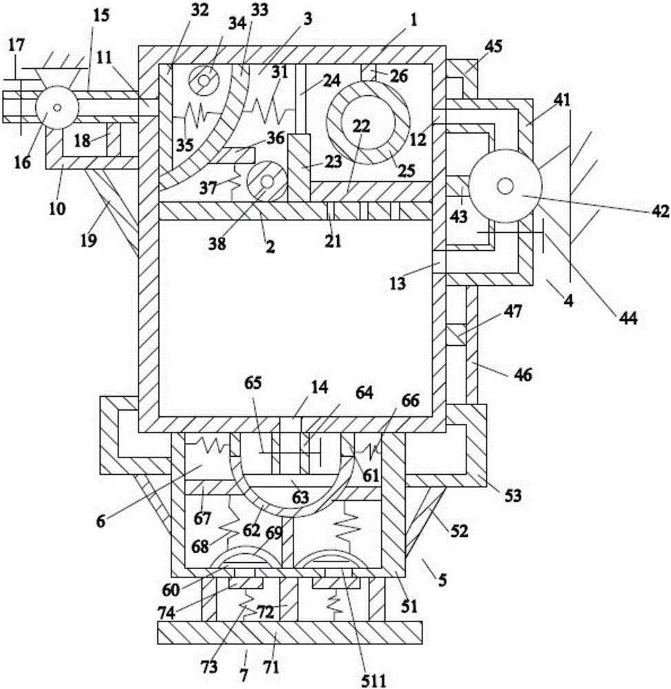
[0019] Such as figure 1 As shown, the power distribution cabinet of the present invention includes a cabinet body 1, a baffle plate 2 accommodated in the cabinet body 1, a first filter device 3 located above the baffle plate 2, and a filter device 3 located on the right side of the cabinet body 1. The circulation device 4 , the support device 5 located below the cabinet body 1 , the second filter device 6 arranged on the support device 5 , and the bottom plate device 7 located below the support device 5 .
[0020] Such as figure 1As shown, the cabinet body 1 is a hollow cuboid, the cabinet body 1 is placed vertically, and the cabinet body 1 is provided with a first through hole 11 on its left surface and a second through hole on its right surface. 12. The third through hole 13, the fourth through hole 14 on its lower surface, the air intake pipe 15 on its left side, the first blower 16 on the air intake pipe 15, the first valve 17, the The first vertical rod 18 below the air...
PUM
Abstract
An electric power distribution cabinet comprises a cabinet body, a baffle plate, a first filter device, a circulation device, a support device, a second filter device and a bottom plate device, a first through hole, a second through hole, a third through hole, a fourth through hole, an air inlet pipe, a first fan, a first valve, a first vertical rod, a first support rod and a first inclined rod are arranged on the cabinet body, a fifth through hole, a first sponge block, a first vertical plate, a first filter net, a first water pipe and a first connection rod are arranged on the baffle plate, the first filter device comprises a first spring, a second sponge block, a second filter net, a second water pipe, a second spring, a first transverse rod, a third spring and a third water pipe, the circulation device comprises a circulation pipe, a second fan, a second valve, a second transverse rod, a second support, a first support rod and a third transverse rod, the support device comprises a frame body, a second inclined rod and a third support, and the second filter device comprises a sponge ring, a support frame, a third filter net and an air outlet pipe. The temperature in the cabinet can be effectively reduced, and an electrical device component is protected.
Description
technical field [0001] The invention relates to the technical field of electric equipment, in particular to an electric power distribution cabinet. Background technique [0002] When the existing power distribution cabinet is used, the temperature in the cabinet will rise due to the heat generated by the electrical components. When the temperature reaches a certain value, it will affect the normal operation of the electrical components, and even cause damage to the electrical components in severe cases. [0003] Therefore, it is necessary to provide a new technical solution to solve the above technical problems. Contents of the invention [0004] The object of the present invention is to provide a power distribution cabinet that can effectively solve the above technical problems. [0005] In order to solve the above technical problems, the present invention adopts the following technical solutions: [0006] A power distribution cabinet, the power distribution cabinet inc...
Claims
Application Information
Patent Timeline
Application Date:The date an application was filed.
Publication Date:The date a patent or application was officially published.
First Publication Date:The earliest publication date of a patent with the same application number.
Issue Date:Publication date of the patent grant document.
PCT Entry Date:The Entry date of PCT National Phase.
Estimated Expiry Date:The statutory expiry date of a patent right according to the Patent Law, and it is the longest term of protection that the patent right can achieve without the termination of the patent right due to other reasons(Term extension factor has been taken into account ).
Invalid Date:Actual expiry date is based on effective date or publication date of legal transaction data of invalid patent.