Photosynthetic hydrogen preparation device

A technology for photosynthetic hydrogen production and hydrogen production equipment, which is applied in photobioreactors, biochemical equipment and methods, biochemical instruments, etc., and can solve problems such as excessive auxiliary energy, insufficient reaction, and short contact process between photosynthetic bacteria and organic raw materials , to achieve the effect of low energy consumption

Inactive Publication Date: 2011-02-16
GUANGZHOU UNIVERSITY
View PDF4 Cites 8 Cited by
  • Summary
  • Abstract
  • Description
  • Claims
  • Application Information

AI Technical Summary

Problems solved by technology

The hydrogen production reactor has the following disadvantages: the reaction liquid flows in one direction in the reactor, and the contact process between photosynthetic bacteria and organic materials is short, resulting in insufficient reaction and low hydrogen production rate
However, it also needs to provide an external high-pressure air source device, which consumes more auxiliary energy

Method used


Image

  • Photosynthetic hydrogen preparation device
  • Photosynthetic hydrogen preparation device
  • Photosynthetic hydrogen preparation device

Examples


example 1

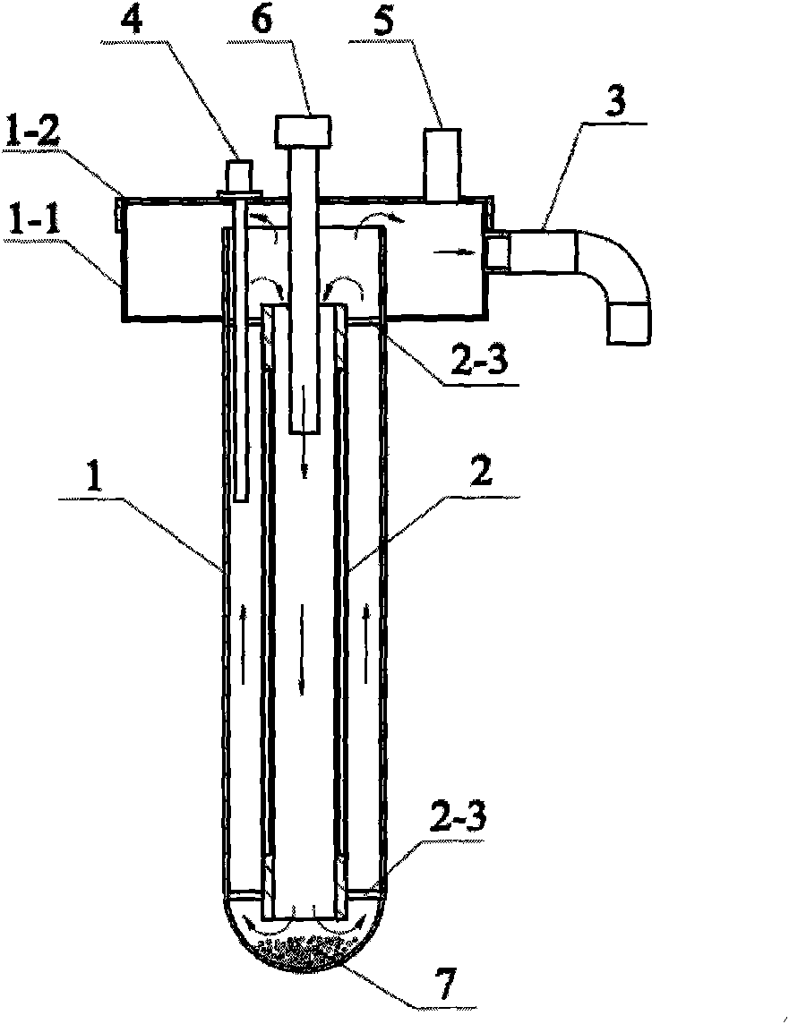
[0017] see figure 1 The reaction cylinder 1 of the photosynthetic hydrogen production device of this embodiment is a cylindrical cylinder with an open upper end and a closed lower end, and an annular groove 1-1 is arranged on the outer side of the upper part, and the top surface of the annular groove 1-1 is higher than the cylindrical cylinder. top of the barrel. A reaction solution outlet 3 is provided on the side wall of the annular groove 1-1, and a cylinder cover 1-2 is provided at the upper end. A reaction liquid inlet pipe 6 is arranged at the center of the top of the cylinder cover 1-2, and an electric heating pipe 4 and a gas outlet 5 are arranged beside the reaction liquid inlet pipe 6 .

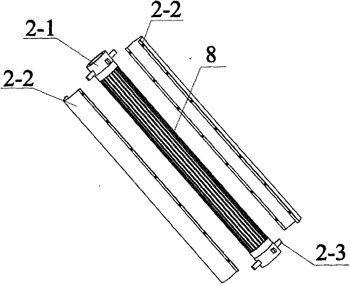
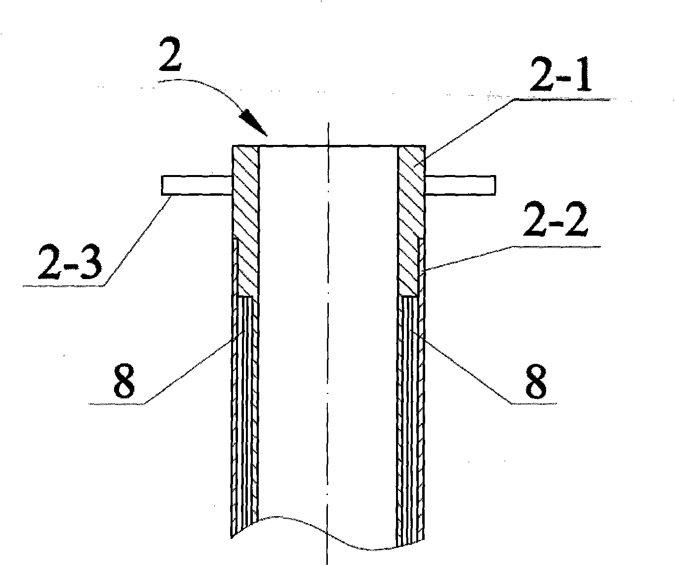
[0018] see Figure 1 ~ Figure 3 , the guide tube 2 is a double-layer structure made of transparent glass, the middle part of its inner tube wall 2-1 is provided with an annular groove, and the wavelength is 500nm fluorescent tube 8 is installed in the annular groove; its outer tub...

example 2

[0020] see Figure 4 , The guide tube in this embodiment is a cylindrical tube 2, the inner and outer walls of which are densely covered with LEDs 2-4, and the head of each LED lamp 2-4 is exposed from the wall of the cylindrical tube 2. In this example, the length of the reaction liquid inlet pipe 6 protruding into the inner cavity of the draft tube 2 is 1 / 3 of the length of the draft tube 2 .

[0021] In this example, other embodiments than the above are the same as in Example 1.

[0022] Describe the working principle of the photosynthetic hydrogen production device of the present invention below in conjunction with embodiment and accompanying drawing:

[0023] see figure 1 , the organic reaction liquid enters the reaction cylinder 1 from the reaction liquid inlet pipe 6 through the guide cylinder 2 under the action of the liquid flow pump. Once the reaction solution is full of reaction cylinder 1 and overflows from the upper end, the newly entered reaction solution will...


PUM

PropertyMeasurementUnit
wavelengthaaaaaaaaaa

Abstract

The invention relates to a microbiology device, in particular to a photosynthetic hydrogen preparation device. The device consists of a cylindrical reaction cylinder (1), a guide flow cylinder (2) coaxially arranged in the reaction cylinder (1) and an electric-heating tube (4) arranged on the upper part of the reaction cylinder (1), wherein a light source is arranged in the cylinder wall of the guide flow cylinder (2); and the upper part of the reaction cylinder (1) is provided with a gas outlet (5) and a reactive fluid outlet (3). The device is characterized in that: a reactive fluid inlet tube (6) is arranged at the top of the reaction cylinder (1); the upper part of the guide flow cylinder (2) extends into the guide flow cylinder (2); and the elevation of the reactive fluid outlet (3) is higher than that of the upper end face of the guide flow cylinder (2). The photosynthetic hydrogen preparation device can push reactive fluid in the guide flow cylinder to flow downwards based on the pressure of a flow pump and the gravitational potential energy of the reactive fluid so as to accelerate the circulatory flow of the reactive fluid in a reactor. The device has good hydrogen preparation effect and obvious effect of helping to lower energy consumption.

Description

technical field [0001] The invention relates to a microbiology device, in particular to a biological hydrogen production device. Background technique [0002] Biological hydrogen production is a bioengineering technology that uses the physiological metabolism of microorganisms to decompose organic matter to produce hydrogen. It is of great significance to deal with organic waste and solve energy shortage problems. At present, the methods of biological hydrogen production mainly include photolysis of water to produce hydrogen, fermentation of hydrogen and photosynthesis of hydrogen. Hydrogen production by photolysis of water is a hydrogen production method in which microalgae and cyanobacteria use solar energy as energy and water as raw material to decompose water into hydrogen and oxygen through photosynthesis and its unique hydrogen production enzyme system; fermentation hydrogen production is heterogeneous Anaerobic bacteria use carbohydrates and other organic matter to p...

Claims


Application Information

Patent Timeline
Patent Type & Authority Applications(China)
IPC IPC(8): C12M1/107
CPCC12M21/04C12M41/12C12M23/06C12M21/02C12M31/10
Inventor 江帆
Owner GUANGZHOU UNIVERSITY
Why Eureka
Try Eureka