Ultra-high-speed and super-cavitation catamaran with hydrofoils

A catamaran and supercavitation technology, which is applied in the direction of hull, hull design, ship construction, etc., can solve the problems of reduced propulsion efficiency, inability to effectively increase the speed of the ship, and low propulsion efficiency, so as to increase the speed of the ship and eliminate the phenomenon of cavitation Effect

Active Publication Date: 2014-03-26
缪德贵
View PDF13 Cites 17 Cited by
  • Summary
  • Abstract
  • Description
  • Claims
  • Application Information

AI Technical Summary

Problems solved by technology

[0007] (3) Ultra-high-speed propulsion: There are mainly two types of propulsion devices for ships today. One is propeller propulsion, and the other is water jet propulsion. Propeller propulsion is the most common. The disadvantage is that during work, the negative pressure generated in front of the propeller produces cavitation, and the higher the speed, the more obvious the cavitation, and the appearance of cavitation has a great negative impact on the propulsion efficiency. The higher the speed of the propeller, The greater the negative pressure, the more obvious the cavitation phenomenon and the lower the propulsion efficiency
Therefore, some ships with high speed today use water-jet propulsion devices. Due to the particularity of its design, compared with propeller propulsion, water-jet propulsion is more efficient than propeller propulsion within a certain speed range. However, Since water jet propulsion is a non-linear motion, when the propulsion speed exceeds a certain limit value, the propulsion efficiency will suddenly drop sharply, so that the speed cannot be effectively increased. Therefore, in order to obtain higher propulsion speed and better propulsion efficiency, it is necessary to Redesign of the propulsion device on the basis of new theory

Method used


Image

  • Ultra-high-speed and super-cavitation catamaran with hydrofoils
  • Ultra-high-speed and super-cavitation catamaran with hydrofoils
  • Ultra-high-speed and super-cavitation catamaran with hydrofoils

Examples


Embodiment Construction

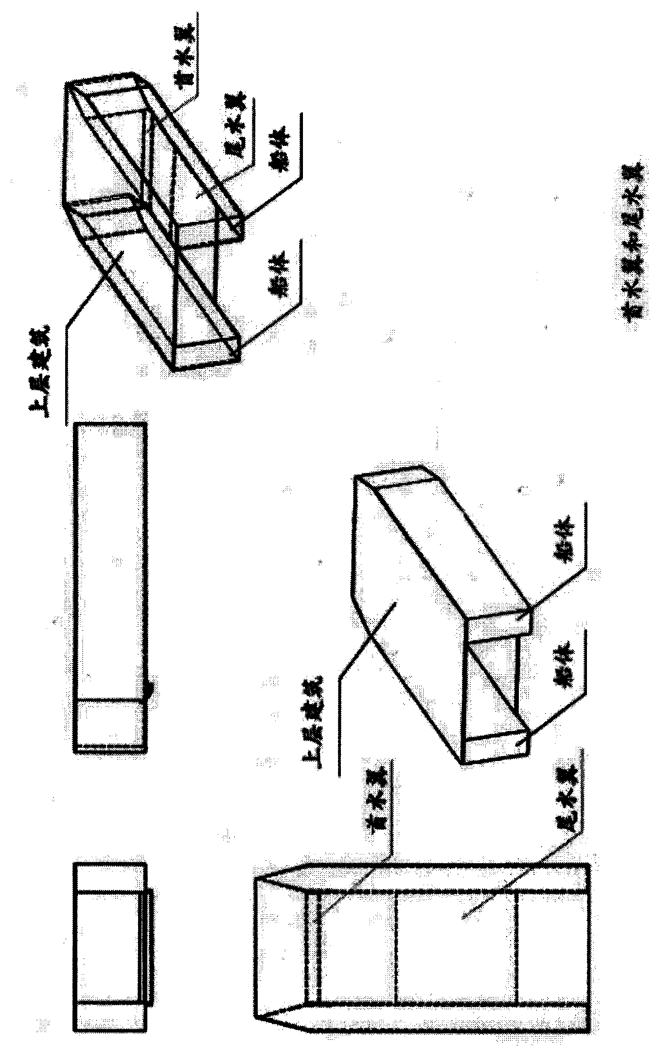
[0023] (1) The bow hydrofoil is an adjustable ascending wing installed in the bow of the ship. During sailing, the lift of the hull is controlled. The stern hydrofoil is the main hydrofoil extending equidistantly from the center of gravity to the bow and aft, and is connected to the bottom plane of the two hulls on the same plane. , Is a fixed main hydrofoil.

[0024] (2) Use a ventilation device to connect the lift surface of the hydrofoil and the front transverse edge of the bottom surface of the hull. When sailing, the hydrofoil and the bottom surface of the ship are separated from the water by a thin air film, and the hydrofoil and the bottom of the ship achieve supercavitation.

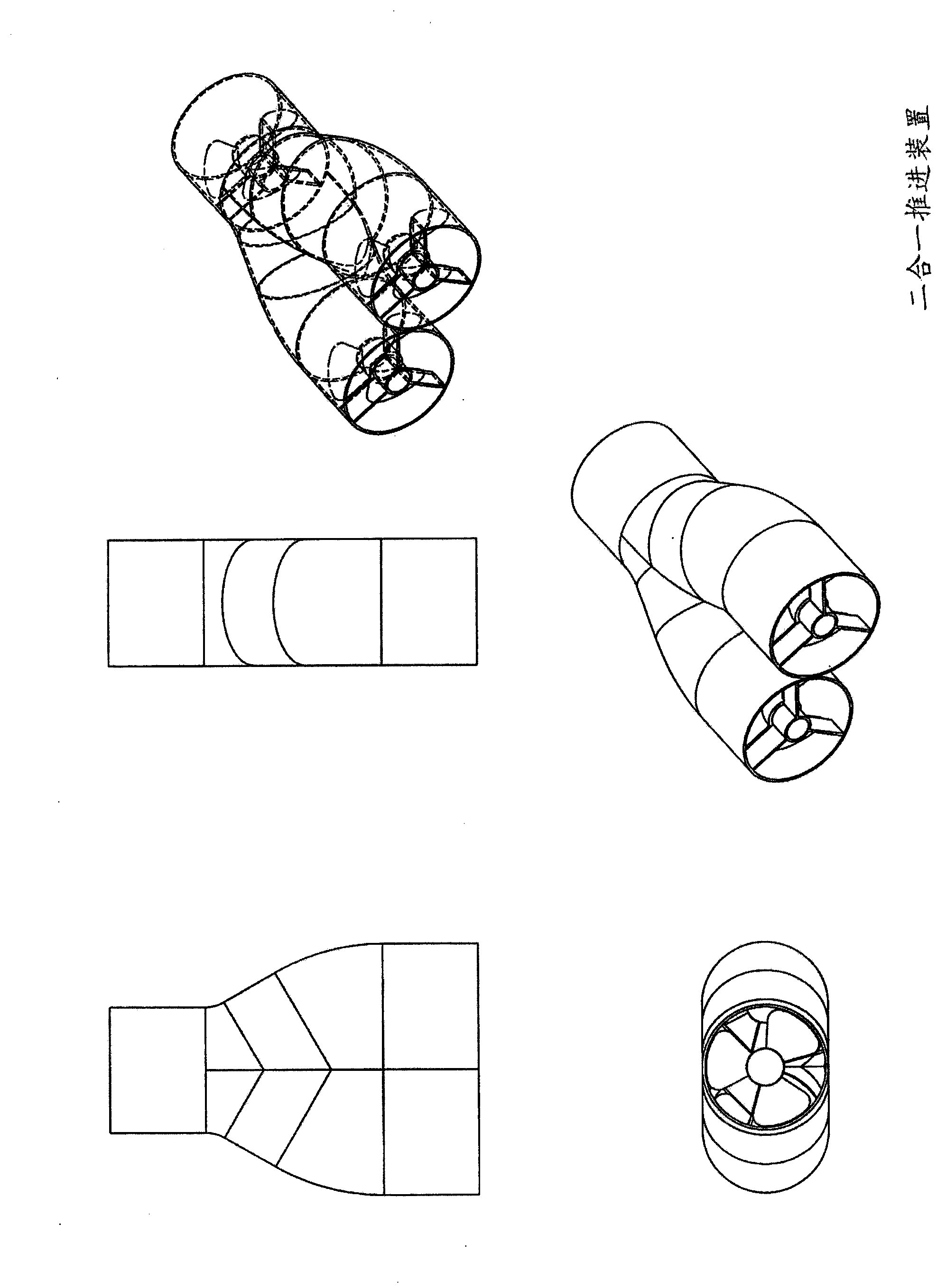
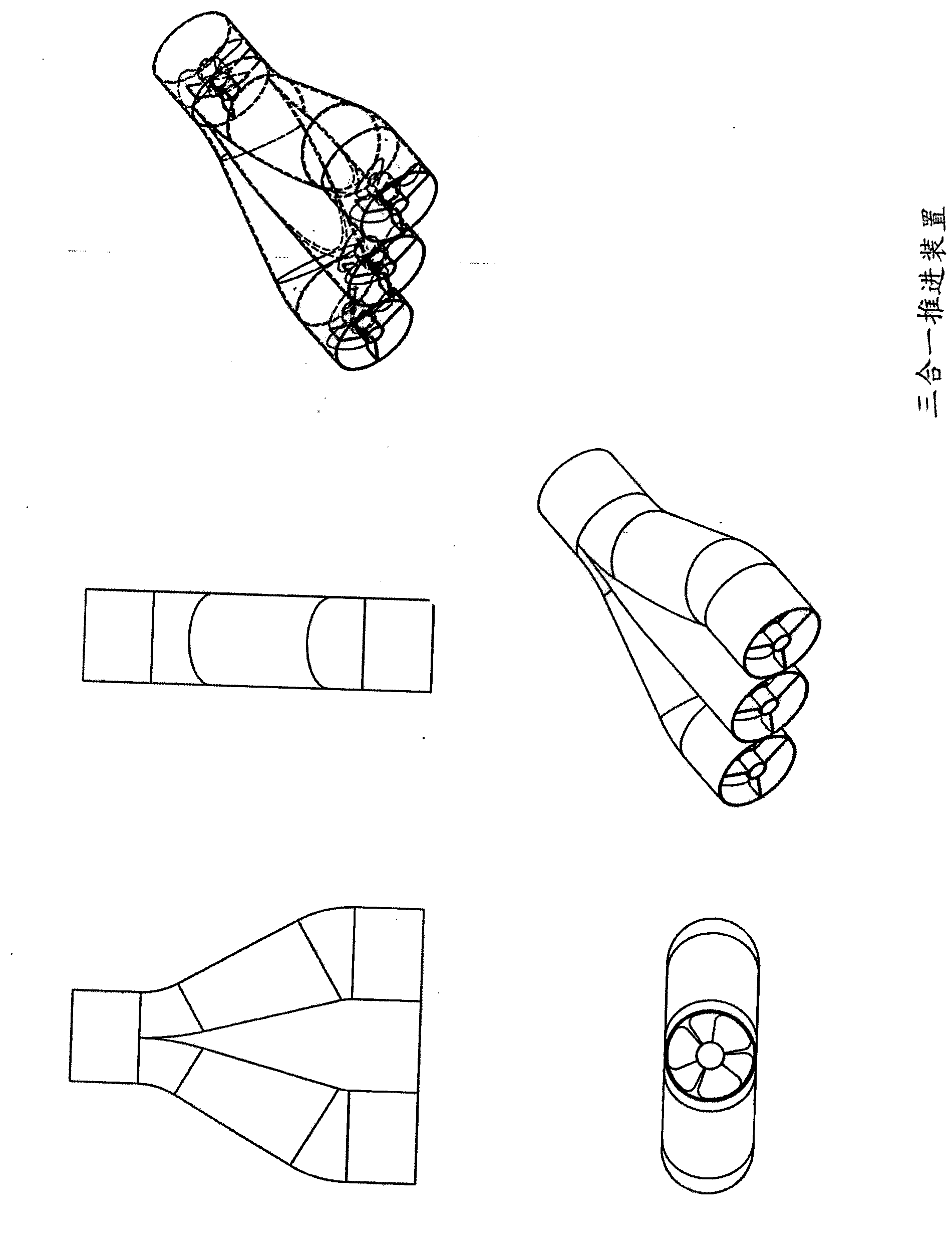
[0025] (3) Combine two water inlet pipes in the middle, and a water outlet at the back is a two-in-one channel combined propeller propulsion device, and three water inlet pipes are combined in the middle, and a water outlet at the back is a three-in-one. One channel combined propeller propulsion devic...


PUM


Abstract

The invention relates to an ultra-high-speed and super-cavitation catamaran with hydrofoils. The head hydrofoil and the tail hydrofoil are arranged between two ship bodies of the catamaran, the head hydrofoil is an adjustable rising hydrofoil, the tail hydrofoil is a fixed main hydrofoil which extends from the lateral gravity center of the catamaran to the head and the tail of the catamaran by equal distances, the head hydrofoil supplies rising force to the catamaran in the sailing process, the tail hydrofoil is the main hydrofoil and supports the ship bodies to sail on the water, and the tonnage of the catamaran can be increased from current hundreds of tons to tens of thousands of tons or more due to the hydrofoils. Due to the rising force surfaces of the hydrofoils and the two ship bodies of the catamaran, super-cavitation is achieved, and therefore viscous resistance between the catamaran bottom and water and viscous resistance between the hydrofoils and water can be reduced by more than 90%. A plurality of water inlet pipes are combined in the middle, a propelling device of a shrouded combined type propeller of a water outlet pipe is arranged at the rear portion of the catamaran, negative pressure is reduced on the water inlet opening in front of the catamaran so that no cavitation phenomenon can happen to the propeller, and the propelling speed is multiplied due to the water outlet opening in the rear portion of the catamaran.

Description

Technical field: [0001] (1) The application of catamaran hydrofoils reduces the wave-making resistance of the ship during navigation by more than 90%. The application of large-area hydrofoils of catamaran hydrofoils can increase the displacement of hydrofoils by hundreds of tons. As large as 10,000 tons, with the continuous maturity of technology, there is still room for the displacement to continue to increase. [0002] (2) The hydrofoil and the bottom of the catamaran hydrofoil ship achieve supercavitation, which can reduce the viscous resistance of the ship by 90%. [0003] (3) The application of the ducted combined propeller propulsion device prevents the occurrence of cavitation, and can increase the speed of a supercavitating catamaran hydrofoil with a displacement of 10,000 tons to over a hundred knots. Background technique: [0004] Knowing from the ship’s resistance law, the ship’s resistance increases rapidly with the increase in speed. The viscous resistance is approxima...

Claims


Application Information

Patent Timeline
Patent Type & Authority Applications(China)
IPC IPC(8): B63B1/24B63B1/38
CPCY02T70/10
Inventor 缪德贵
Owner 缪德贵
Why Eureka
Try Eureka