Cable-drive steel wire rope connecting device

A technology for connecting devices and wire rope joints, applied in the direction of transmission elements or pulley ropes or cables, textile cables, belts/chains/gears, etc. Reliability, reduce control difficulty, reduce the effect of force intensity

Active Publication Date: 2014-03-26
DALIAN HUARUI HEAVY IND GRP CO LTD
View PDF7 Cites 4 Cited by
  • Summary
  • Abstract
  • Description
  • Claims
  • Application Information

AI Technical Summary

Problems solved by technology

[0003] Without a wire rope tension detection device, the tension of the wire rope cannot be accurately detected, so that the tension of the wire rope cannot be accurately controlled, and it is easy to cause uneven loads on multiple wire ropes, thereby affecting the life of the wire rope and even breaking the wire rope;
[0004] In addition, in the existing steel wire rope joint form, the bending moment on the pin bearing is too large, the size of the component is large, and the weight of the mechanism is too large, which affects the rational layout of the mechanism

Method used


Image

  • Cable-drive steel wire rope connecting device
  • Cable-drive steel wire rope connecting device
  • Cable-drive steel wire rope connecting device

Examples


Embodiment Construction

[0019] The present invention will be further described below in conjunction with drawings and embodiments.

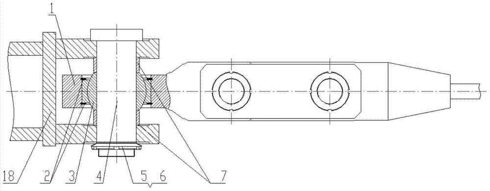
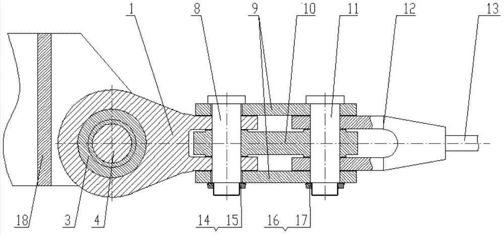
[0020] The embodiment is to drive the signal receiving device of the astronomical telescope—the cable-driven wire rope connection device of the feed cabin, including the fork 1, the retaining ring 2, the joint bearing 3, the pin shaft I4, the round nut I5, the washer I6, and the spacer 7 , pin shaft II8, protective plate 9, tension sensor 10, pin shaft III11, steel wire rope joint 12, steel wire rope 13, round nut II14, washer II15, round nut III16, washer III17 and connection support 18, the front part of fork 1 is Two horizontal parallel plates, the rear part is a connecting plate, the center of the two horizontal parallel plates in the front is provided with a pin hole, and the center of the rear connecting plate is provided with a joint bearing hole; the front part of the wire rope joint 12 is Two horizontal parallel plates, the front of the two horizontal parallel ...


PUM


Abstract

The invention discloses a cable-drive steel wire rope connecting device which comprises a Y-shaped piece, a check ring, a knuckle bearing, a pin roll I, a spacer sleeve, a pin roll II, a protective plate, a tension sensor, a pin roll III, a steel wire tope connector, a steel wire rope and a connecting support. The Y-shaped piece is connected with the steel wire rope connector through the tension sensor, the connecting support is connected with the Y-shaped piece through the knuckle bearing and the pin roll I, and the connecting base is connected with a cable drive component. The cable-drive steel wire rope connecting device has the advantages that stress conditions of all steel wire ropes can be obtained timely, and a feed source cabin can be controlled more accurately; on the condition that the tension sensor is fractured, the protective plate can maintain connection of the connecting device, support the cable drive component, and prevent the cable drive component from being damaged; the connecting device has no additional bending moment, the stress condition is clear, and safety and reliability are high; the difficulty of control over the multi-freedom-degree motion of the feed source cabin is reduced; the knuckle bearing is used for connecting the connecting support and the Y-shaped piece, so that additional bending moment is prevented from being applied to the Y-shaped piece, stress intensity of the Y-shaped piece is reduced, and reliability of driving a feed source cabinet is improved.

Description

technical field [0001] The invention belongs to a steel wire rope connection device for cable machinery, in particular to an astronomical telescope cable driving steel wire rope connection mechanism. Background technique [0002] The signal receiving device of the telescope used in the astronomical field is the feed cabin. The feed cabin is arranged with multiple degrees of freedom and driven by several wire ropes. In the prior art, the connection method between the wire rope and the feed cabin is mainly a combination of a pin shaft and a rope clamp. Install. Its disadvantages are: [0003] Without a wire rope tension detection device, the tension of the wire rope cannot be accurately detected, so that the tension of the wire rope cannot be accurately controlled, and it is easy to cause uneven loads on multiple wire ropes, thereby affecting the life of the wire rope and even breaking the wire rope; [0004] In addition, in the existing steel wire rope joint form, the bendi...

Claims


Application Information

Patent Timeline
Patent Type & Authority Applications(China)
IPC IPC(8): F16G11/00
Inventor 张金晶徐宏伟马洪斌李辉朱文白
Owner DALIAN HUARUI HEAVY IND GRP CO LTD
Why Eureka
Try Eureka