
Borderless touch screen

A touch screen, borderless technology, applied in the touch field, can solve the problem of reducing the width of the visible area of ​​the protection panel, and achieve the effect of expanding the scope of the visible area

Active Publication Date: 2019-01-22
ANHUI JINGZHUO OPTICAL DISPLAY TECH CO LTD
View PDF5 Cites 0 Cited by
  • Summary
  • Abstract
  • Description
  • Claims
  • Application Information

AI Technical Summary

Problems solved by technology

[0003] The present invention provides a borderless touch screen, which is used to solve the problem that both sides of the protective panel of the touch screen need to be coated with light-shielding ink to cover the lead area and reduce the width of the visible area of ​​the protective panel. The specific solution is as follows:

Method used


Image

  • Borderless touch screen
  • Borderless touch screen
  • Borderless touch screen

Examples


Embodiment 1

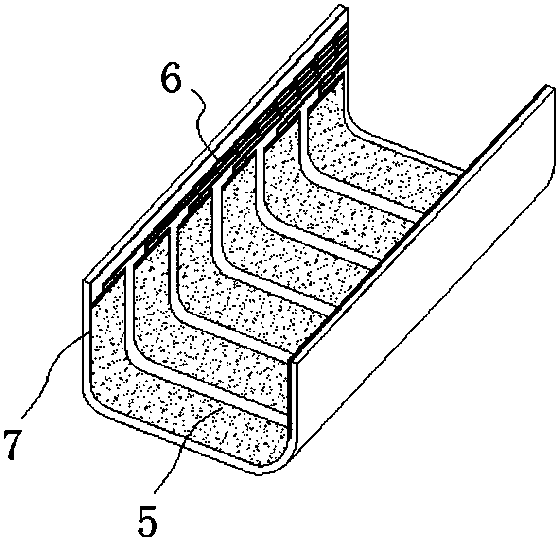
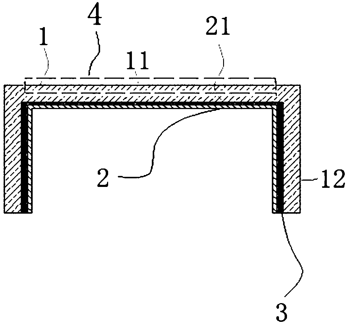
[0027] The structural representation of embodiment 1 is as image 3 , Figure 4 As shown, the connection between the top plate 11 and the side plate 12 of the protective panel 1 is connected at right angles. exist figure 2 , the two side plates 12 are connected at right angles to the top plate 11, in image 3 Among them, one side plate 12 is connected to the top plate 11 at right angles, and the other side plate 12 is connected to the top plate 11 smoothly.

Embodiment 2

[0028] The structural representation of embodiment 2 is as Figure 5 As shown, the top plate 11 and the side plate 12 are both straight and flat, and the side plate 12 is perpendicular to the top plate 11. The joint between the top plate 11 and the side plate 12 is an arc-shaped joint, thereby avoiding stress concentration at the joint and easy damage. And in injection molding or thermocompression molding, the arc-shaped connecting portion is more demolded during manufacture. The thickness d of the top plate 11 and the side plate 12 is the same, and the value of d is 0.3mm-1.0mm. The inner radius r of the arc-shaped connection part is 0.5mm-5mm, the outer radius R=r+d, and the arc surface is a 90° arc. The width W1 of the top plate 11 is 20mm-200mm; the width W2 of the side plate 12 is 2mm-20mm. There is no light-shielding layer 3 inside the arc-shaped connection part, and the arc-shaped connection part is a transparent visible area 4.

Embodiment 3

[0029] The structural representation of embodiment 3 is as Figure 7 As shown, the top plate 11 is arc-shaped, and the side plate 12 is straight. The top plate 11 and the side plate 12 are smoothly connected. The light-shielding layer 3 is arranged inside the side board 12 , and the top board 11 is a transparent visible area 4 .


PUM


Abstract

The invention provides a touch screen without a border. The touch screen comprises a protective panel and a conducting film. The protective panel comprises a top plate and a side plate, wherein the top plate and the side plate are formed integrally, the side plate extends from one side of the top plate and is not located in the same plane as the top plate, the top plate is a transparent visible area, and the inner side of the side plate is provided with a shading layer so as to form a shielding area. The conducting film is attached to the protective panel and comprises a substrate and a conducting layer arranged on the substrate; the conducting layer comprises an induction area and a lead area, wherein the induction area is located in the middle of the substrate, the lead area is located at the edge of the substrate, transparent electrodes used for sensing touch operation are arranged inside the induction area, leads connected with the transparent electrodes are arranged in the lead area, and the lead area right is aligned with the shielding area of the protective panel. According to the touch screen without the border, the top plate of the touch screen is not provided with ink, as a result, the range of the visible area can be broadened to the maximum with no need for increasing the size of electronic equipment, and an electronic device can be decreased in size and provided with a larger screen beneficially.

Description

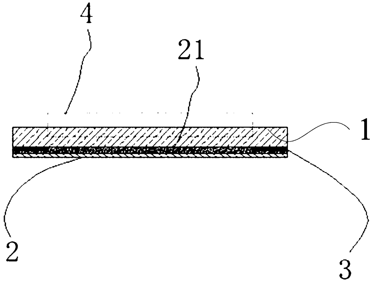
technical field [0001] The invention relates to the field of touch technology, in particular to a borderless touch screen. Background technique [0002] The touch screen is widely used in various electronic devices, such as cameras, mobile phones, MP4 and other electronic devices, which are mainly combined with the display screen to perform graphic touch operations and receive input signals such as touch. The structure of the existing touch screen is as figure 1 As shown, it includes a protective panel 1 and a conductive film 2 attached to the protective panel 1. The conductive film is attached to the protective panel 1 through an optical adhesive layer 21. The conductive film 2 includes a substrate and is arranged on the substrate. The conductive layer includes a transparent conductive pattern located in the middle of the substrate and leads located on the edge of the substrate, and the leads are electrically connected to the conductive pattern for transmitting electrical ...

Claims


Application Information

Patent Timeline
Patent Type & Authority Patents(China)
IPC IPC(8): G06F3/041
Inventor 刘伟徐炫
Owner ANHUI JINGZHUO OPTICAL DISPLAY TECH CO LTD
Learn More