Print control apparatus and printing system

A printing control and printing output technology, which is applied in the direction of digital output to printing units, instruments, calculations, etc., can solve the problems of not being able to give printing instructions, and not being able to view the preview image of the printed object file

Active Publication Date: 2014-03-26
KONICA MINOLTA INC
View PDF11 Cites 0 Cited by
  • Summary
  • Abstract
  • Description
  • Claims
  • Application Information

AI Technical Summary

Problems solved by technology

[0010] However, the technique described in this Patent Document 2 is based on the premise that a print instruction is given from a device (personal computer) on which a printer driver is installed.
Therefore, on an external terminal (portable terminal, etc.) that does not have a printer driver installed, a print instruction cannot be given, and as a result, a preview image of a file to be printed cannot be viewed.

Method used


Image

  • Print control apparatus and printing system
  • Print control apparatus and printing system
  • Print control apparatus and printing system

Examples


no. 1 Embodiment approach >

[0094]

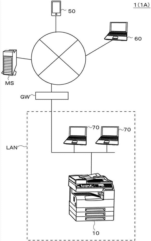
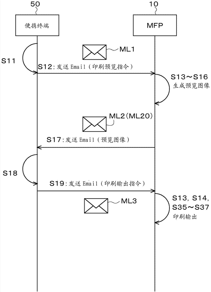
[0095] figure 1 It is a figure which shows the printing system 1 (1A in detail) of 1st Embodiment. Such as figure 1 As shown, this printing system 1A includes an MFP (Multi-Functional Peripheral) 10 and a portable terminal 50 . In addition, the printing system 1A also includes personal computers 60 , 70 and the like.

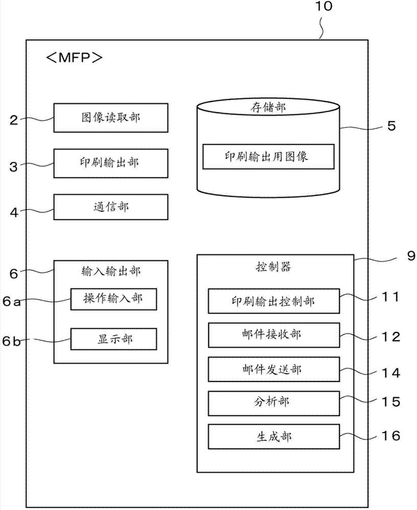
[0096] The MFP 10 functions as a print control device, and also functions as a print output device.

[0097] In addition, portable terminal 50 is an external terminal device of MFP 10 and is also referred to as an external terminal. Likewise, the personal computers 60, 70 are also referred to as external terminals.

[0098] Each element 10, 50, 60, 70 in this system 1 is connected to the network NW, respectively. The network NW is composed of a LAN (Local Area Network), the Internet, and the like. In addition, the connection method to the network NW may be a wired connection or a wireless connection. For example, the MFP 10 and the personal com...

no. 2 Embodiment approach >

[0173] The second embodiment is a modified example of the first embodiment. Hereinafter, differences from the first embodiment will be described emphatically.

[0174] In the above-mentioned first embodiment, an example of designating a single print setting "2 in 1" in the email ML1 was exemplified.

[0175] In this second embodiment, an example is exemplified in which a plurality of print settings (specifically, three print settings “magnification”, “image shift”, and “2 in 1”) are specified in combination in the email ML1. Furthermore, in the second embodiment, it is determined whether or not the combined setting of the plurality of print settings (hereinafter also referred to as "composite setting") corresponds to the "combination prohibition setting" (setting for prohibiting combined application). ). Then, when it is determined that the composite setting corresponds to the combination prohibition setting, at least one print setting of an available combination among a plu...

no. 3 Embodiment approach >

[0211] The third embodiment is a modified example of the second embodiment. Hereinafter, differences from the second embodiment will be described emphatically.

[0212] In the above-mentioned second embodiment, the image data MG10 ( Figure 20 ) are added to the single email ML2 (ML21) (refer to Figure 21 as well as Figure 22 etc.) after sending.

[0213] In this third embodiment, an example is exemplified in which a plurality of preview images MG1 to MG5 are individually attached to a plurality of emails ML2 (ML22a to ML22e) and then transmitted (see Figure 25 as well as Figure 26 Wait).

[0214] Figure 25It is a figure which shows the operation|movement in the system 1 of 3rd Embodiment. In the MFP 10 of the third embodiment, the Figure 13 Same action. However, in step S23, execution such as Figure 28 action shown.

[0215] Such as Figure 28 As shown, in step S24 ( S242 ), the MFP 10 (generating unit 16 ) generates individual preview images MG1 to MG5 for...


PUM


Abstract

The present invention relates to a print control apparatus and a printing system, and provides a technique that enables a user to easily browse a print preview image of a file to be printed on an external terminal in which a printer driver is not installed. A Multi-Functional Peripheral (MFP) 10 receives a first e-mail (ML1) that includes a print preview instruction from an external terminal (50), analyzes the first e-mail (ML1) and detects the print preview instruction from the first e-mail (ML1). Moreover, the MFP generates a preview image on the basis of the print preview instruction, attaches the preview image to a second e-mail (ML2) and sends the second e-mail toward the external terminal (50).

Description

technical field [0001] The present invention relates to printing technology, in particular to printing preview technology. Background technique [0002] In recent years, printing devices such as MFPs have been equipped with a function of printing and outputting attachments of electronic mail (E-mail) (also referred to as “E-mail reception printing”). Specifically, the attachment is printed and output by sending an e-mail to which the file to be printed is attached to the e-mail address of the printing apparatus (see Patent Document 1). [0003] With such a function, it is possible to print and output a file to be printed by MFP from an external terminal (personal computer, portable terminal, etc.) that does not have a printer driver installed. [0004] [Prior Art Literature] [0005] 【Patent Literature】 [0006] [Patent Document 1] (Japanese) Unexamined Patent Application Publication No. 2001-306272 [0007] [Patent Document 2] (Japanese) Unexamined Patent Application Pu...

Claims


Application Information

Patent Timeline
Patent Type & Authority Applications(China)
IPC IPC(8): G06F3/12
CPCG06F3/1205G06F3/1228G06F3/1292G06F3/1256
Inventor 森田光贵福冈香加藤知和上田博贵
Owner KONICA MINOLTA INC
Why Eureka
Try Eureka