Supercharge Your Innovation With Domain-Expert AI Agents!

multi-frequency antenna

A multi-frequency antenna and grounding plate technology, applied in the direction of antenna, antenna coupling, antenna grounding device, etc., can solve the problems of poor isolation of PIFA antenna, poor radiation efficiency of PIFA antenna, serious influence of antenna radiation shielding effect, etc.

Active Publication Date: 2017-02-08
FOXCONN (KUNSHAN) COMPUTER CONNECTOR CO LTD +1
View PDF8 Cites 0 Cited by
  • Summary
  • Abstract
  • Description
  • Claims
  • Application Information

AI Technical Summary

Problems solved by technology

However, the location of this mechanism has a serious impact on the shielding effect of antenna radiation, resulting in poor radiation efficiency of PIFA antennas
Moreover, the location of this mechanism is easily occupied by other cables from the rotating shaft, which greatly limits the space for placing antennas, resulting in poor isolation between adjacent PIFA antennas

Method used


Image

  • multi-frequency antenna
  • multi-frequency antenna
  • multi-frequency antenna

Examples


Embodiment Construction

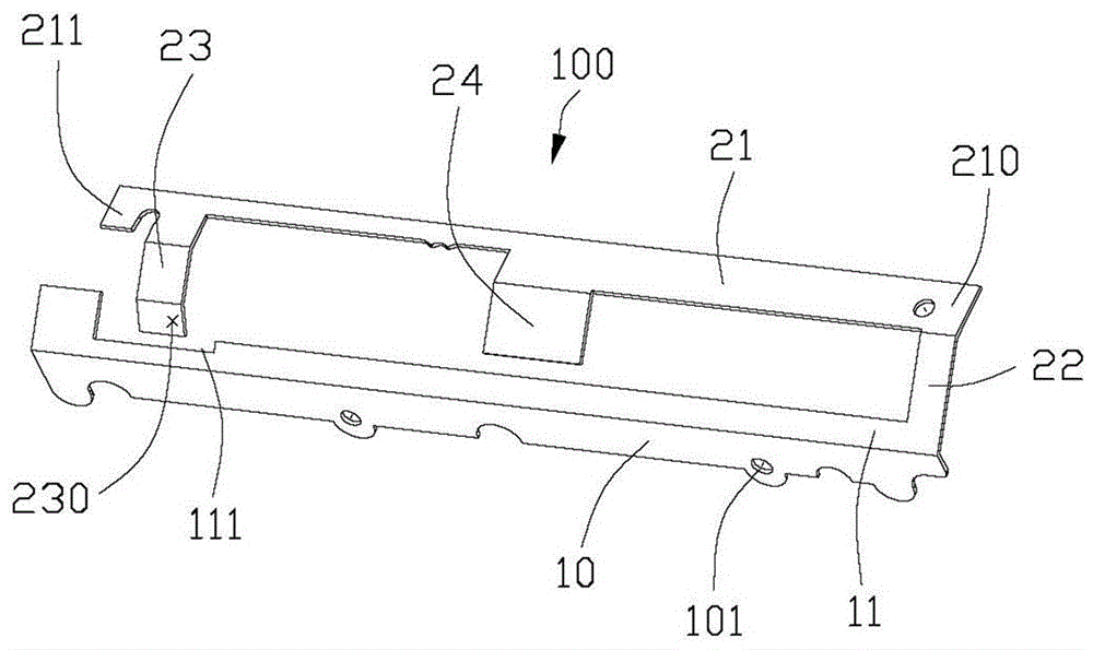
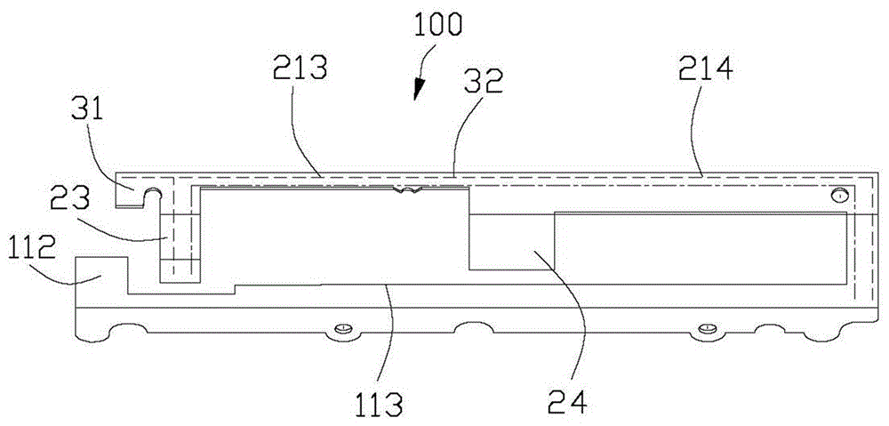
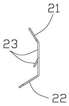
[0015] The specific implementation manner of the multi-frequency antenna 100 of the present invention will be described in detail below with reference to the accompanying drawings.

[0016] see Figure 1 to Figure 3 As shown, the multi-frequency antenna 100 of the present invention is made by punching and cutting a metal plate. The multi-frequency antenna 100 includes a longitudinal ground plate 10 and a radiation portion extending from a longitudinal edge of the ground plate. The specific structure of the radiation portion will be described below . The ground plate 10 is provided with several holes 101 on the other longitudinal edge for fixing the antenna.

[0017] The radiating portion includes a first longitudinal arm 21, a first transverse arm 23 and a second transverse arm 24. The first longitudinal arm 21 extends along the longitudinal direction and is spaced apart from the ground plate 10. The long arm has opposite first end 211 and second end 210 , and the second end...


PUM


Abstract

The invention discloses a multi-band antenna which comprises a longitudinal grounding plate, a first longitudinal arm parallel to the grounding plate, a connecting arm for connecting the grounding plate with the first longitudinal arm, and a first horizontal arm extending from the first longitudinal arm to the grounding plate, wherein the grounding plate is provided with a longitudinal edge extending in a longitudinal direction; the first longitudinal arm extends in the longitudinal direction, is spaced from the grounding plate, and is provided with a first tail end and a second tail end, which are opposite to each other; the second tail end of the first longitudinal arm is connected with the longitudinal edge of the grounding plate through the connecting arm; the first horizontal arm extends from the part, close to the first tail end, of the first longitudinal arm to the grounding plate, is spaced from the grounding plate, and is provided with a signal feeder point; the first longitudinal arm is divided into two radiation parts with different lengths by the first horizontal arm, and the radiation parts are positioned on the two sides of the first horizontal arm. Compared with the prior art, the multi-band antenna has the advantages that the radiation efficiency is improved to a certain extent, and the radiation isolation degree is improved.

Description

[0001] 【Technical field】 [0002] The invention relates to a multi-frequency antenna. [0003] 【Background technique】 [0004] In notebook computers, especially under the mechanical conditions of the all-metal magnesium-aluminum back cover, the position of the antenna is forced to move between the rotating shaft and the body. However, the location of this mechanism has a serious impact on the shielding effect of the antenna radiation, resulting in poor radiation efficiency of the PIFA antenna. Moreover, the location of this mechanism is likely to be occupied by other cables from the rotating shaft, which greatly limits the space for placing the antennas, resulting in poor isolation between adjacent PIFA antennas. [0005] Therefore, it is necessary to design a multi-frequency antenna to overcome the above problems. [0006] 【Content of invention】 [0007] The object of the present invention is to provide a multi-frequency antenna with improved radiation efficiency. [0008]...

Claims


Application Information

Patent Timeline
Patent Type & Authority Patents(China)
IPC IPC(8): H01Q1/36H01Q1/48H01Q1/52H01Q5/10
Inventor 戴隆盛
Owner FOXCONN (KUNSHAN) COMPUTER CONNECTOR CO LTD
Features
  • R&D
  • Intellectual Property
  • Life Sciences
  • Materials
  • Tech Scout
  • Unparalleled Data Quality
  • Higher Quality Content
  • 60% Fewer Hallucinations
Learn More