Supercharge Your Innovation With Domain-Expert AI Agents!

A compact large-angle scanning leaky-wave antenna based on alumina ceramic material

An alumina ceramic, leaky wave antenna technology, applied in the directions of antennas, antenna grounding devices, electrical components, etc., can solve the problems of the overall size of the antenna being difficult to reduce, the capacity per unit length is limited, and it is difficult to achieve size reduction, etc. Effective aperture, reduced distortion, and high compactness

Active Publication Date: 2022-05-27
HEBEI UNIV OF TECH
View PDF7 Cites 0 Cited by
  • Summary
  • Abstract
  • Description
  • Claims
  • Application Information

AI Technical Summary

Problems solved by technology

On the one hand, designing a leaky wave antenna, like a phased array antenna, needs to obtain a larger beam scanning range to meet the requirements of signal space coverage; on the other hand, it is necessary to achieve a compact antenna structure without affecting the performance of the antenna. Floquet's cycle theorem shows that when the traditional periodic leaky-wave antenna works with high-order modes, its unit spacing is not less than an integer multiple of the half-wavelength of the operating frequency, so the overall size of the antenna is difficult to reduce; while for another type of antenna based on composite Quasi-periodic leaky wave antennas made of left and right hand materials, interdigitated capacitors, and parallel plate capacitor structures can provide limited capacitance per unit length and low radiation efficiency, and it is also difficult to achieve size reduction

Method used


Image

  • A compact large-angle scanning leaky-wave antenna based on alumina ceramic material
  • A compact large-angle scanning leaky-wave antenna based on alumina ceramic material
  • A compact large-angle scanning leaky-wave antenna based on alumina ceramic material

Examples


Embodiment 1

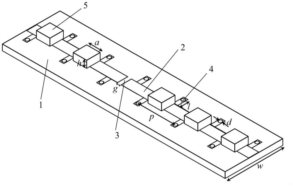
[0035]This embodiment provides a compact large-angle scanning leaky wave antenna based on alumina ceramic material (antenna for short, see figure 1 ), the side-fire operating frequency of the antenna is 5.8GHz, and it is characterized in that: the antenna includes three parts: a grounded dielectric substrate 1, a composite left and right-handed microstrip transmission line and an alumina ceramic block 5, wherein:

[0036] The grounded dielectric substrate 1 is a dielectric substrate with full copper cladding on the back, which supports the propagation of quasi-transverse electromagnetic waves in the main mode.

[0037] The composite left and right-handed microstrip transmission line is composed of a 50-ohm rectangular microstrip line 2 arranged on the front surface of the dielectric substrate, and a shorting pin matching branch 4. Periodically arranged rectangular slits 3 are arranged on the 50-ohm rectangular microstrip line 2, and the rectangular slits 3 are along the In the...


PUM

PropertyMeasurementUnit
thicknessaaaaaaaaaa
widthaaaaaaaaaa

Abstract

The invention discloses a compact large-angle scanning leaky-wave antenna based on alumina ceramic material, which belongs to the field of antennas. The antenna consists of three parts: a grounded dielectric substrate, a composite left and right-handed microstrip transmission line, and an alumina ceramic block. The composite left and right-handed microstrip transmission line consists of a 50-ohm rectangular microstrip line on the front of the dielectric substrate, periodically arranged rectangular slots, and short-circuit nails to match the branches. composition. Since the introduced rectangular slit can be equivalent to a magnetic dipole, its E-plane far-field pattern is omnidirectional. When the beam points away from the side-beam direction, it can make up for the loss of gain. Therefore, it has a large-angle scanning feature and effectively increases signal coverage. At the same time, the introduced alumina ceramic material has high dielectric constant, high quality factor and low loss characteristics. Compared with the traditional leaky wave antenna, the size of the antenna is greatly reduced, and the radiation efficiency of the antenna can be maintained at a high level.

Description

technical field [0001] The invention belongs to the field of antennas, and relates to a compact large-angle scanning leaky wave antenna based on alumina ceramic materials. Background technique [0002] Leaky-wave antennas belong to the category of traveling-wave antennas, which are characterized by beams that are highly directional and can scan with frequency. In recent years, with the rapid development of wireless communication, the application scenarios of leaky wave antennas have greatly increased, and higher requirements have been put forward for their performance indicators. On the one hand, the design of leaky-wave antennas, like phased array antennas, needs to obtain a larger beam scanning range to meet the requirements of signal space coverage; Froquet's cycle theorem shows that when the traditional periodic leaky-wave antenna works with high-order modes, the unit spacing is not less than an integer multiple of the half wavelength of the operating frequency, so it i...

Claims


Application Information

Patent Timeline
Patent Type & Authority Patents(China)
IPC IPC(8): H01Q1/38H01Q1/48H01Q3/00H01Q15/00
CPCH01Q1/48H01Q1/38H01Q3/005H01Q15/0086
Inventor 郑宏兴李子巍
Owner HEBEI UNIV OF TECH
Features
  • R&D
  • Intellectual Property
  • Life Sciences
  • Materials
  • Tech Scout
  • Unparalleled Data Quality
  • Higher Quality Content
  • 60% Fewer Hallucinations
Learn More