Differential protection device based on Faraday magneto-optical effect
A differential protection device, Faraday magneto-optical technology, applied in the direction of automatic disconnection emergency protection device, emergency protection circuit device, measuring device, etc., can solve the problem of large error components and other problems
- Summary
- Abstract
- Description
- Claims
- Application Information
AI Technical Summary
Problems solved by technology
Method used
Image
Examples
specific Embodiment approach 1
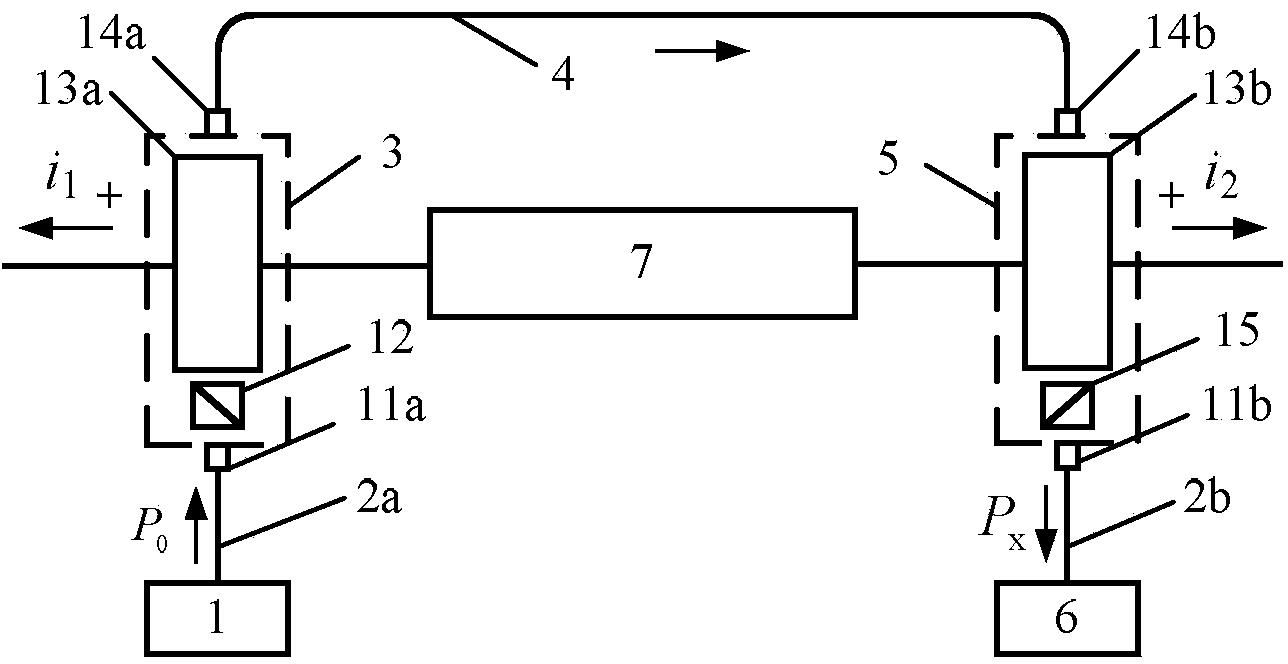
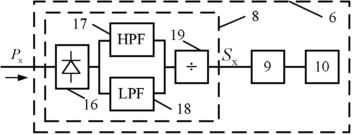
[0014] Specific implementation mode one: the following combination figure 1 Describe this embodiment, the differential protection device based on the Faraday magneto-optical effect described in this embodiment, it includes a light source 1, a first multimode optical fiber 2a, a second multimode optical fiber 2b, a first optical current sensor 3, a polarization maintaining optical fiber 4. The second optical current sensor 5 and the electronic processing unit 6;
[0015] The first optical current sensor 3 and the second optical current sensor 5 are arranged at both ends of the protection interval 7 in the power system, and the light beam emitted by the light source 1 is sent to the first optical current sensor 3 through the first multimode optical fiber 2a. The optical signal output end of the first optical current sensor 3 is connected to the optical signal input end of the second optical current sensor 5 through the polarization maintaining optical fiber 4, and the optical si...
specific Embodiment approach 2
[0017] Specific implementation mode two: the following combination figure 1 This embodiment will be described. This embodiment will further describe the first embodiment. The first optical current sensor 3 includes a first multimode fiber collimator 11a, a polarizer 12, a first Faraday magneto-optical element 13a and a first protection Polarizing fiber collimator 14a; The second optical current sensor 5 includes a second polarization-maintaining fiber collimator 14b, a second Faraday magneto-optical element 13b, a polarizer 15 and a second multimode fiber collimator 11b;
[0018] The polarizer 15 of the second optical current sensor 5 is arranged at an angle of 45° relative to the polarizer 12 of the first optical current sensor 3;
[0019] The light signal sent by the light source 1 is sent to the first multimode fiber collimator 11a of the first optical current sensor 3 through the first multimode fiber 2a, and the first multimode fiber collimator 11a injects the received li...
specific Embodiment approach 3
[0020] Specific implementation mode three: the following combination figure 1 This embodiment will be described. This embodiment will further describe the second embodiment. The current i 1 The direction flowing from the inner side to the outer side of the protection zone 7 is positive, and the current i 2 The direction of flow from the inner side to the outer side of the protection zone 7 is positive.
PUM
 Abstract
Description
Claims
Application Information
 - R&D
- Intellectual Property
- Life Sciences
- Materials
- Tech Scout
- Unparalleled Data Quality
- Higher Quality Content
- 60% Fewer Hallucinations
Browse by: Latest US Patents, China's latest patents, Technical Efficacy Thesaurus, Application Domain, Technology Topic, Popular Technical Reports.
© 2025 PatSnap. All rights reserved.Legal|Privacy policy|Modern Slavery Act Transparency Statement|Sitemap|About US| Contact US: help@patsnap.com


