
Compressor

A compressor and valve body technology, applied in the field of compressors, can solve the problems that ordinary compressors cannot adapt to different working conditions, and achieve the effect of improving cooling and heating efficiency

Active Publication Date: 2014-04-16
ZHUHAI GREE REFRIGERATION TECH CENT OF ENERGY SAVING & ENVIRONMENTAL PROTECTION
View PDF5 Cites 18 Cited by
  • Summary
  • Abstract
  • Description
  • Claims
  • Application Information

AI Technical Summary

Problems solved by technology

[0005] The purpose of the present invention is to provide a compressor to solve the technical problem that ordinary compressors cannot adapt to different working conditions

Method used


Image

  • Compressor
  • Compressor
  • Compressor

Examples


Embodiment Construction

[0022] The embodiments of the present invention will be described in detail below with reference to the accompanying drawings, but the present invention can be implemented in many different ways defined and covered by the claims.

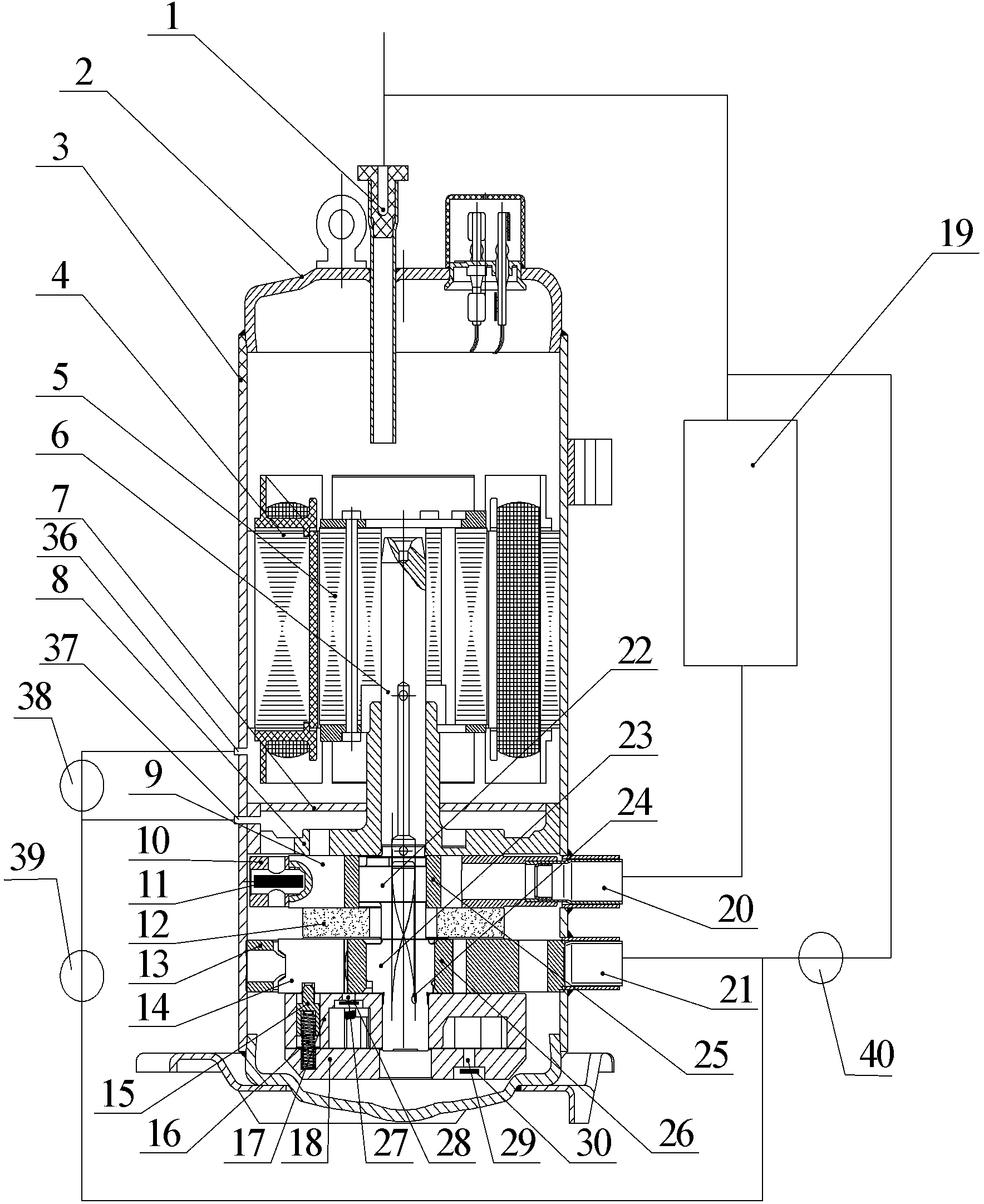
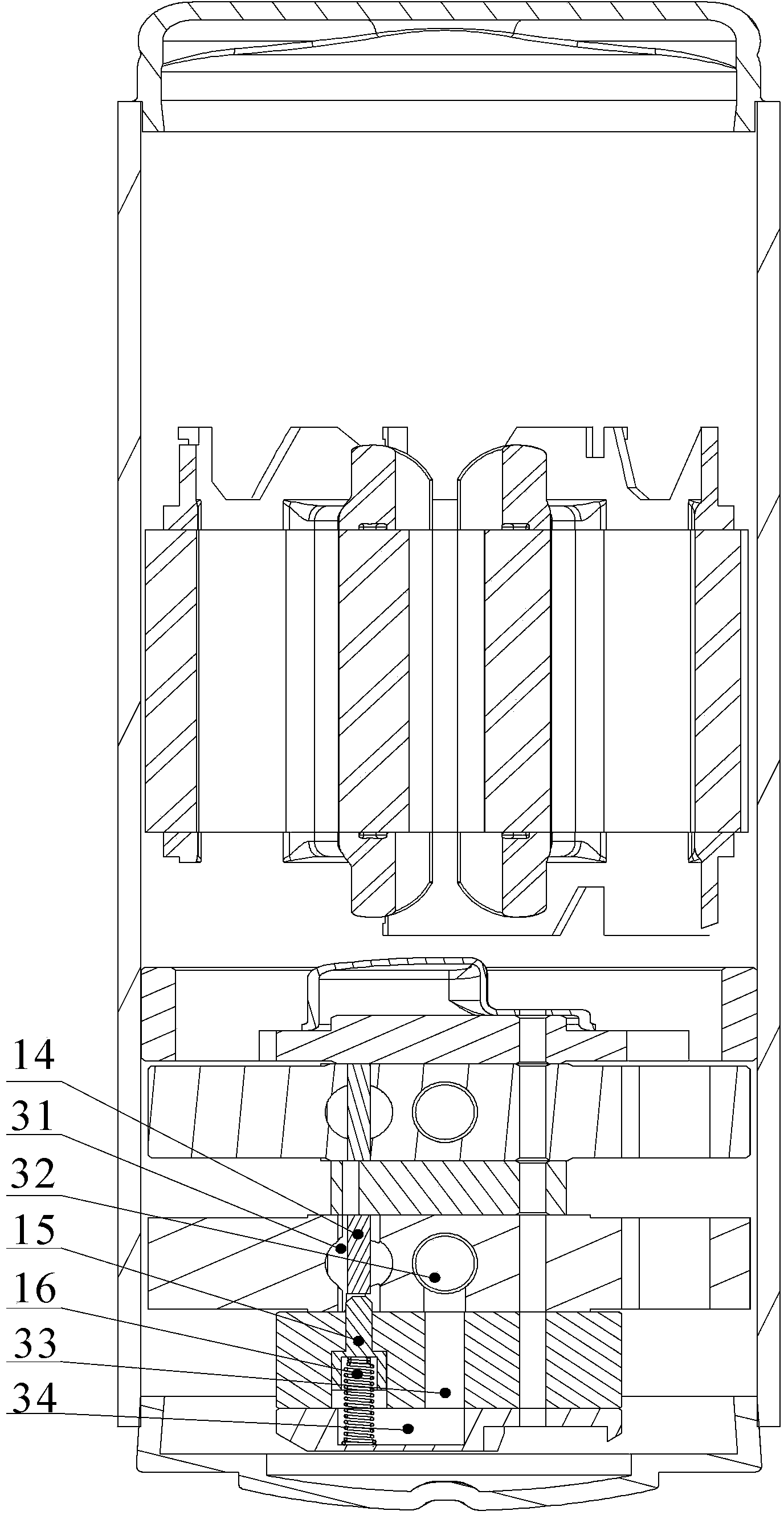
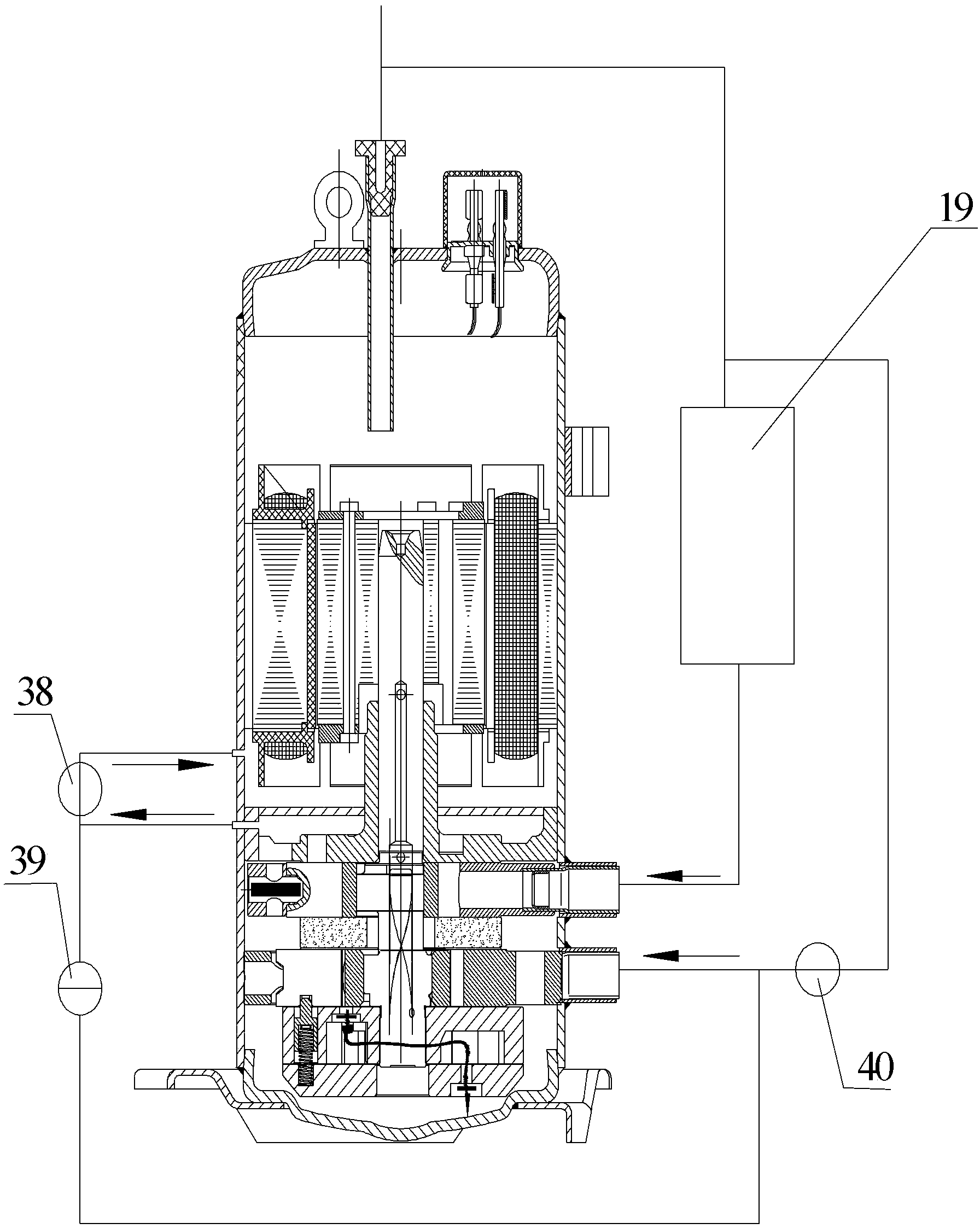
[0023] see Figure 1 to Figure 5 , according to the compressor of the present invention, comprising a housing 3 on which an exhaust pipe 1 is arranged; a crankshaft 6 disposed inside the housing 3, including a first eccentric portion 22 and a second eccentric portion 23; a first cylinder 10, cooperate with the first eccentric part 22 through the first roller 25; the second cylinder 13 cooperate with the second eccentric part 23 through the second roller 26; the middle partition 12 is arranged between the first cylinder 10 and the second cylinder In the middle of 13, the first cylinder 10 and the second cylinder 13 are connected; the first flange 8 is connected with the first cylinder 10; the first cover plate 7 is set on the first flange 8; the seco...


PUM


Abstract

The invention provides a compressor, which comprises a shell; a crankshaft; a first air cylinder; a second air cylinder; a middle partition board; a first flange; a first cover plate; a second flange; a first vent hole communicated with an exhaust pipe; a second vent hole, which is arranged on the shell between the first flange and the first cover; a first valve body, which is arranged between the first vent hole and the second vent hole; a second valve body, which is disposed between the second vent hole and a second air suction pipe arranged on the second air cylinder; a third valve body, which is arranged between the exhaust pipe and the second air suction pipe. By adding three body bodies, switching of the compressor under three states can be realized, and different needs under different working conditions can be realized. Especially under severe working conditions (ultra low temperature heating or high temperature refrigeration), two-stage operation of the compressor can be realized, and the refrigeration and heating efficiency can be improved. Under ordinary heating or refrigeration conditions, single cylinder or double-cylinder operation can be chosen according to different needs.

Description

technical field [0001] The present invention relates to the field of compressors, in particular, to a compressor. Background technique [0002] In the prior art, there is a double-cylinder variable-capacity rotor hermetic compressor, which is characterized in that a sealed vane chamber is arranged behind the vane of a cylinder, and the vane chamber is kept at low pressure while the cylinder is at high pressure to forcibly keep the vane and roller in phase. Separation, thereby stopping the compression of a cylinder to change the displacement of the compressor to achieve variable capacity. [0003] The existing technology uses the principle of pressure difference to control the vanes to realize the unloading of one cylinder to change the displacement of the compressor. The oil supply structure for vane lubrication is provided in the closed vane chamber, and the upper and lower two cylinders and single cylinder can be obtained respectively through two four-way valves. run. ...

Claims


Application Information

Patent Timeline
Patent Type & Authority Applications(China)
IPC IPC(8): F04C23/00
Inventor 刘强梁社兵杨国蟒徐嘉邓丽颖
Owner ZHUHAI GREE REFRIGERATION TECH CENT OF ENERGY SAVING & ENVIRONMENTAL PROTECTION
Learn More