A hydraulically driven rotary sprinkler head with adjustable speed and its speed regulating method
A water-driven, rotary technology, applied in the direction of spraying devices with movable outlets, spraying devices, etc., to achieve strong operability and reliable operation
- Summary
- Abstract
- Description
- Claims
- Application Information
AI Technical Summary
Problems solved by technology
Method used
Image
Examples
Embodiment Construction
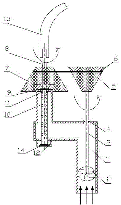
[0020] Such as figure 1 As shown in the figure, a hydraulically driven rotary sprinkler head with adjustable speed includes pipe 1, impeller 2, shaft A3, sealing ring A4, inverted bevel gear belt 5, belt 6, forward bevel gear belt 7, shaft B8, plane Bearing A9, water inlet hole 10, sealing ring B11, plane bearing B12, nozzle 13, pipe groove 14; the impeller 2 is placed in the pipe 1, the center of the impeller 2 is fixedly connected with the axis A3, and the impeller 2 and the axis A3 rotate together The shaft A3 passes through the inner wall of the pipeline 1, and a boss is provided inside and outside the pipeline 1, the purpose of which is to locate the shaft A3; the contact between the boss and the shaft A3 and the pipeline 1 is provided with a sealing ring A4, and the purpose is to prevent water leakage; The central axis of the inverted bevel gear belt 5 is axis A3, and there are gear rings with different circumferences in the horizontal direction on the inverted bevel gea...
PUM
 Abstract
Description
Claims
Application Information
 - R&D
- Intellectual Property
- Life Sciences
- Materials
- Tech Scout
- Unparalleled Data Quality
- Higher Quality Content
- 60% Fewer Hallucinations
Browse by: Latest US Patents, China's latest patents, Technical Efficacy Thesaurus, Application Domain, Technology Topic, Popular Technical Reports.
© 2025 PatSnap. All rights reserved.Legal|Privacy policy|Modern Slavery Act Transparency Statement|Sitemap|About US| Contact US: help@patsnap.com

