Rear-view mirror of automobile allowing adjusting location

A technology for automotive rearview mirrors and rearview mirrors, applied in the field of automotive rearview mirrors, can solve problems such as poor driver's vision, and achieve the effects of small impact effects and continuous acceleration curves

Active Publication Date: 2014-04-30
CHERY AUTOMOBILE CO LTD
View PDF2 Cites 8 Cited by
  • Summary
  • Abstract
  • Description
  • Claims
  • Application Information

AI Technical Summary

Problems solved by technology

[0003] The purpose of the present invention is to propose a position-adjustable car rearview mirror, which can adjust its position along the front and rear directions of the vehicle body, so as to solve the problem of driving caused by the inappropriate distance between the driver and the rearview mirror. The problem of poor vision of the driver is more conducive to the driver to observe the road conditions and ensure driving safety

Method used


Image

  • Rear-view mirror of automobile allowing adjusting location
  • Rear-view mirror of automobile allowing adjusting location

Examples


Embodiment 1

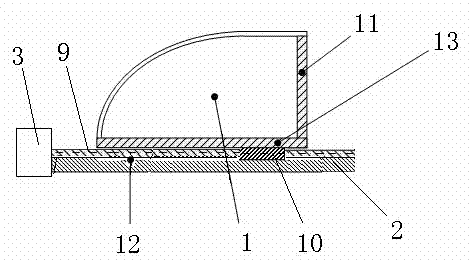
[0018] Such as figure 1 As shown, the position-adjustable automobile rearview mirror of this embodiment includes a rearview mirror housing 1 and a mount 2, and the mount 2 is equipped with a motor 3, a transmission mechanism and a guide rail 12 extending along the front and rear directions of the automobile body; The rearview mirror housing 1 is slidably mounted on the guide rail 12, and the bottom of the rearview mirror housing 1 is provided with a limit slide bar 13 cooperating with the guide rail 12, so as to prevent the rearview mirror housing 1 from breaking away from the guide rail 12; The motor 3 cooperates with the transmission mechanism to drive the rearview mirror housing 1 to move along the guide rail 12 .

[0019] After the driver adjusts the sitting posture, check the rearview mirror. When the front and rear positions of the rearview mirror need to be adjusted, the driver can start the motor 3, and utilize the motor 3 and the transmission mechanism to drive the re...

Embodiment 2

[0028] Such as figure 2 As shown, the position-adjustable automobile rearview mirror of this embodiment includes a rearview mirror housing 1 and a mount 2, and the mount 2 is equipped with a motor 3, a transmission mechanism and a guide rail 12 extending along the front and rear directions of the automobile body; The rearview mirror housing 1 is slidably mounted on the guide rail 12, and the bottom of the rearview mirror housing 1 is provided with a limit slide bar 13 cooperating with the guide rail 12, so as to prevent the rearview mirror housing 1 from breaking away from the guide rail 12; The motor 3 cooperates with the transmission mechanism to drive the rearview mirror housing 1 to move along the guide rail 12 .

[0029] After the driver adjusts the sitting posture, check the rearview mirror. When the front and rear positions of the rearview mirror need to be adjusted, the driver can start the motor 3, and utilize the motor 3 and the transmission mechanism to drive the r...


PUM


Abstract

The invention provides a rear-view mirror of an automobile allowing adjusting position. The position of the rear view mirror can be adjusted transversely along the direction of the bodywork, so that the problem of poor vision for driving which is caused by an inappropriate distance between a driver and the rear view mirror is solved so as to be helpful in observing traffic and ensuring safety. The rear-view mirror comprises a rear view mirror shell and a mounting seat, wherein the mounting seat is provided with a motor, a transmission mechanism and a guide rail which extends transversely along the direction of the bodywork. The rear view mirror shell is arranged on the guide rail in a sliding mode, a limiting slider matched with the guide rail is arranged at the bottom of the rear view mirror, so that the situation that the rear view mirror is derailed from the guide rail can be avoided. The motor is matched with the diving mechanism and the rear view mirror shell can be driven to move along the guide rail. When the rear-view mirror needs to be adjusted transversely, the driver can turn on the motor, the rear view shell can be driven to move along the guide rail through the motor and the driving mechanism to enable the position of the rear-view mirror to suit personal habits.

Description

technical field [0001] The invention belongs to the technical field of automobile manufacturing, in particular to an automobile rearview mirror. Background technique [0002] At present, with the continuous increase of car ownership, there are more and more driving accidents. Therefore, for driving safety, the driver's perspective when driving is getting more and more attention. Ordinary rearview mirrors are generally flat mirrors or convex mirrors. In order to increase the driver's field of vision, methods such as variable curvature design of rearview mirrors, combinations of lenses with different curvatures, and adjustable spatial 3D angles have gradually been applied in automotive rearview mirrors. Due to the different sizes of drivers and the different steering wheel positions designed by OEMs, when different drivers enter the cockpit, they generally need to adjust the front, rear, left and right positions of the seats. When the seat position is changed, the driver nee...

Claims


Application Information

Patent Timeline
Patent Type & Authority Applications(China)
IPC IPC(8): B60R1/07
Inventor 梁厅
Owner CHERY AUTOMOBILE CO LTD
Why Eureka
Try Eureka