Method for calculating near-field radar echo characteristics of moving object based on beam decomposition and local irradiation

A technology of moving targets and partial irradiation, applied in the direction of radio wave reflection/re-radiation, use of re-radiation, radio wave measurement system, etc., can solve problems such as complex near-field problems, only regular targets can be calculated, and memory surges, etc. achieve the effect of clear physical meaning

Inactive Publication Date: 2014-05-07
XIDIAN UNIV
View PDF1 Cites 16 Cited by
  • Summary
  • Abstract
  • Description
  • Claims
  • Application Information

AI Technical Summary

Problems solved by technology

[0003] The echo calculation of electrically large (geometric size much larger than the radar wavelength) size moving target under local beam irradiation is also a problem to be solved. Although analytical methods and numerical methods can obtain more accurate results, they are limited by the orthogonal coordinate system And the limitation of computer memory, it can only calculate the problem of regular targets or complex targets with small size
The physical optics method is an approximation method that can quickly calculate the scattering problem of targets with complex shapes in the high-frequency region, but the commonly used physical optics method is generally based on far-field conditions, and near-field problems tend to become more complicated
Wide beam incidence can increase the memory required for calculations

Method used


Image

  • Method for calculating near-field radar echo characteristics of moving object based on beam decomposition and local irradiation
  • Method for calculating near-field radar echo characteristics of moving object based on beam decomposition and local irradiation
  • Method for calculating near-field radar echo characteristics of moving object based on beam decomposition and local irradiation

Examples


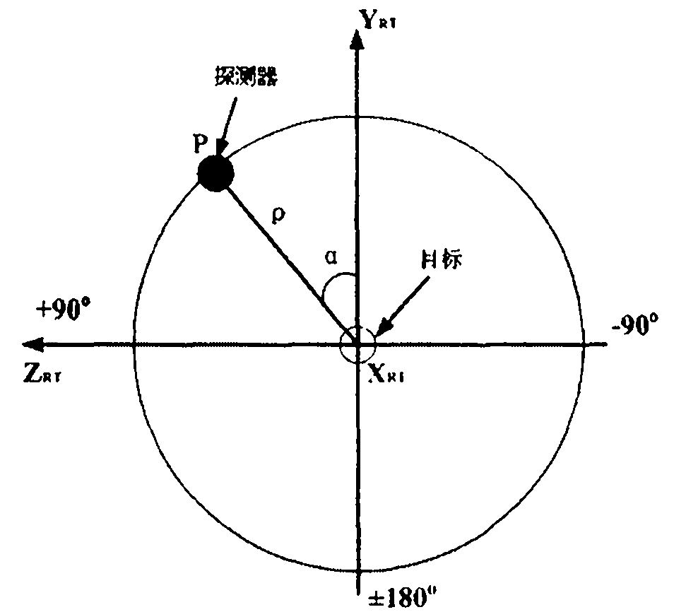
Embodiment Construction

[0026] Below in conjunction with embodiment the present invention is further described.

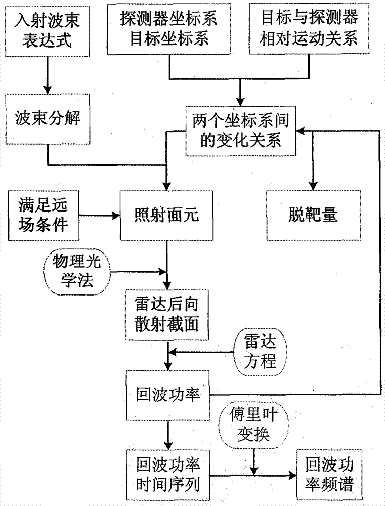
[0027] refer to figure 1 , the specific implementation steps of the present invention are as follows:

[0028] Step 1, determine the radar (detector) coordinate system, the moving target coordinate system and the transformation relationship between them

[0029] Moving targets and radars (detectors) are often defined in local coordinate systems centered on each, and need to be transformed according to different requirements: for example, when determining the amount of miss and the angle of miss, the detector needs to be transformed to the center of the target. In the coordinate system of the center, the detector moves relative to the target; when it is necessary to determine the irradiation conditions of the target components when the beam irradiates the target, the target needs to be transformed into the coordinate system centered on the detector, and the target moves relative to the de...


PUM


Abstract

The invention discloses a method for calculating near-field radar echo characteristics of a moving object based on beam decomposition and local irradiation. The method comprises the steps of determining a coordinate system of radar or a detector, a coordinate system of the moving object and transformation relation between the coordinate systems; determining a relative speed coordinate system of the detector and the object, thereby acquiring a miss distance; providing radar beam description so as to decompose an incident beam, carrying out surface element subdivision on the object, determining the local irradiation area, and judging surface element shielding; meeting a far-field condition by a sub-beam irradiation surface element, and superimposing by using a physical optics method to acquire a backward radar cross section; and acquiring a time series of the power of near-field radar echoes by using a radar equation and the corresponding spectral characteristics. A far-field calculation method is expanded to near-field calculation by using the characteristic that beam decomposition and physical optics are similar to each other locally, and the time series of the power of the near-field radar echoes and the corresponding spectral characteristics. According to the method disclosed by the invention, the far-field calculation method is expanded to the near-field calculation by using the characteristic that the beam decomposition and the physical optics are similar to each other locally, and the time series of the power of the near-field echoes and the corresponding frequency spectrum are calculated by the radar equation.

Description

technical field [0001] The invention relates to a radar echo calculation method, which adopts the calculation method based on beam decomposition and near-field radar echo characteristics of a moving target under partial illumination, and the beam decomposition can effectively reduce the memory requirement for wide beam scattering calculation. Partial illumination makes the target meet the far-field condition in the local area, and the near-field echo can be calculated by the far-field physical optics method, which reduces the computational complexity. Background technique [0002] A large amount of literature has been focused on the far-field characteristics of radar target echoes, but the near-field characteristics of radar targets are also widely used. For example, when measuring in an anechoic chamber, since the distance between the target and the measuring radar is limited by the size of the anechoic chamber, the distance between the target and the radar sometimes cannot...

Claims


Application Information

Patent Timeline
Patent Type & Authority Applications(China)
IPC IPC(8): G01S7/41
CPCG01S7/41G01S13/883
Inventor 吴振森苏翔令狐龙翔张元元
Owner XIDIAN UNIV
Why Eureka
Try Eureka