
Dimming circuit and control method compatible with thyristor dimmer

A dimming circuit and dimmer technology, applied in the direction of electric lamp circuit layout, light source, electric light source, etc., can solve problems such as large leakage current, flicker, affecting the working status of thyristor and LED power supply, and achieve the goal of solving the flicker problem Effect

Inactive Publication Date: 2015-09-23
SHANGHAI ZHANKONGBI ELECTRONICS TECH
View PDF6 Cites 27 Cited by
  • Summary
  • Abstract
  • Description
  • Claims
  • Application Information

AI Technical Summary

Problems solved by technology

In addition, due to the large leakage current of the thyristor dimmer when it is turned off, it will affect the working status of the thyristor and the LED power supply, thereby causing flickering and other phenomena.

Method used


Image

  • Dimming circuit and control method compatible with thyristor dimmer
  • Dimming circuit and control method compatible with thyristor dimmer
  • Dimming circuit and control method compatible with thyristor dimmer

Examples


Embodiment Construction

[0038] The present invention will now be described in further detail with reference to the drawings.

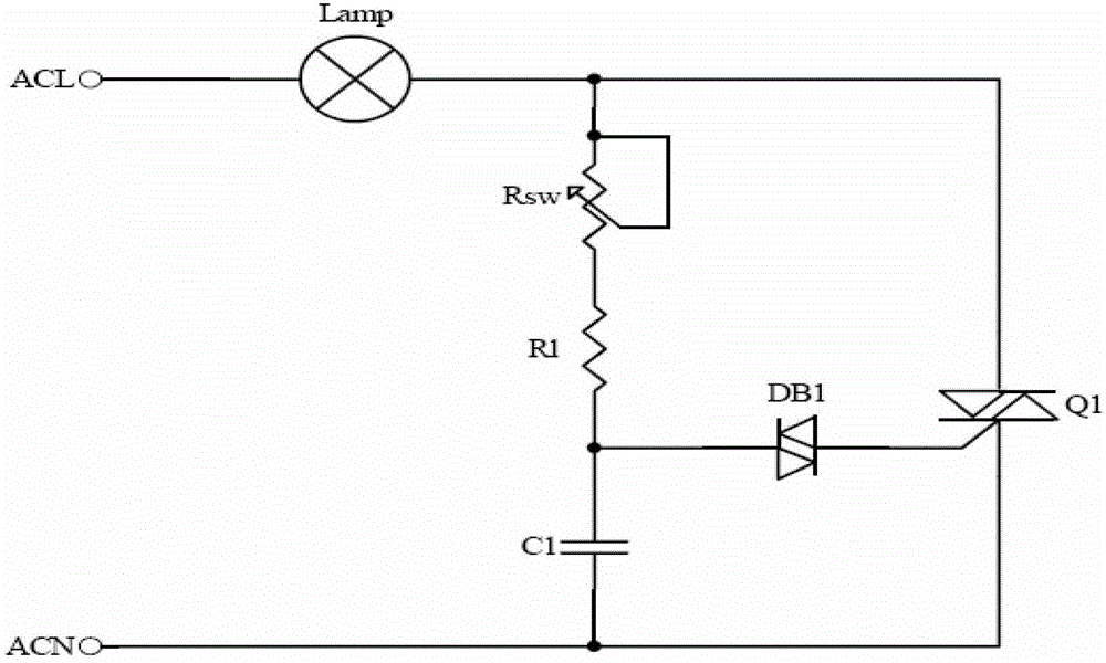
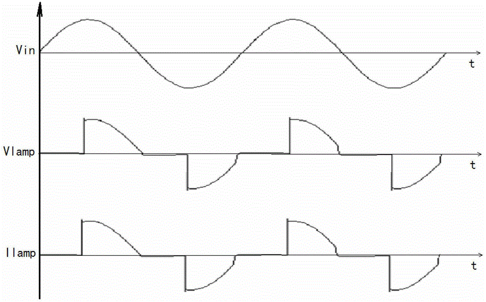
[0039] figure 1 It is a schematic diagram of a traditional incandescent lamp thyristor dimming. Among them, Lamp is an incandescent lamp, Q1 is a triac, DB1 is a triac, Rsw is a variable resistor and connected in series with R1 to charge C1 to generate a variable time constant, thereby controlling the triac's Opening time. In this way, you can experiment with dimming the incandescent lamp. Such as figure 2 The waveform at each point of the phase cut at 90 degrees is shown.

[0040] However, if the LED constant current source is directly connected to the thyristor dimmer, its dimming will have problems. For example, because the LED power supply is a constant current source, and the thyristor dimmer can only phase-cut the input voltage, it can be equivalent to changing the average value of the input voltage. Changing the voltage cannot affect the constant current source. Theref...


PUM


Abstract

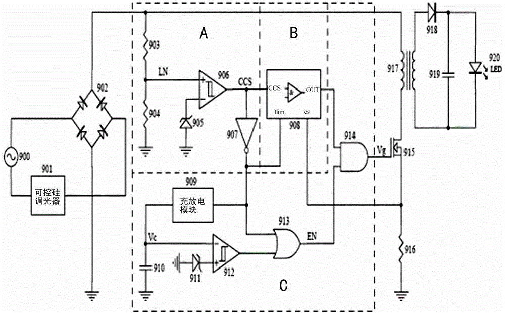
The invention discloses a dimming circuit compatible with a silicon controlled rectifier dimmer and a control method. The dimming circuit includes an input voltage source, a rectification circuit, the silicon controlled rectifier dimmer, a dimming circuit and an output circuit, wherein the input voltage source is connected with the rectification circuit and the silicon controlled rectifier dimmer respectively, the rectification circuit is connected with the dimming circuit, the dimming circuit is connected with the output circuit, and the output circuit includes an isolation transformer, a switch tube, a third sampling resistor, a flyback diode, a filtering capacitor and an output LED load. The dimming circuit compatible with the silicon controlled rectifier dimmer is characterized in that the dimming circuit includes a sampling circuit used for sampling the phase-cut angle of the silicon controlled rectifier dimmer, a control and logic circuit which is controlled by the phase-cut angle, and a phase-cut angle setting circuit which can control the switching on and switching off of the switch tube according to the status of an inputted phase-cut angle. With the dimming circuit compatible with the silicon controlled rectifier dimmer of the invention adopted, the problem of flicker appearing in a traditional dimming process can be effectively solved, and at the same time, a dimming purpose can be achieved.

Description

Technical field [0001] The patent of the invention relates to a dimming circuit and a control method compatible with a thyristor dimmer, in particular to a dimming circuit and a control method for LED lamps by using a traditional incandescent lamp thyristor dimmer. Background technique [0002] Nowadays, due to the rapid development of LED lighting, the original incandescent lamps of tens of watts can be directly replaced with LED bulbs of several watts, which can save a lot of energy. Many dimming methods of incandescent lamps use thyristor dimmers for phase-cut dimming. Because the traditional incandescent lamp is a purely resistive load, it can be directly phase-cut dimmed with a thyristor dimmer. Since traditional incandescent lamps are mostly tens to hundreds of watts, the design of thyristor dimmers is designed with this as a load. However, if this kind of thyristor dimmer is used to dim an LED lamp of several watts, since the LED lamp is not a pure group load, it will ca...

Claims


Application Information

Patent Timeline
Patent Type & Authority Patents(China)
IPC IPC(8): H05B37/02
Inventor 张义陶志波其他发明人请求不公开姓名
Owner SHANGHAI ZHANKONGBI ELECTRONICS TECH
Learn More